
There are practically two ways of configuring the input shaper feature in Klipper firmware. The first is to manually print a tuning tower and measure its ringing artifacts. The second is to use an accelerometer like the ADXL345.
The manual method is less accurate and more time-consuming. In contrast, using an accelerometer automates a lot of the process for you.
We’ve already covered the manual method in our main article on Klipper input shaping. In this article, we will guide you through how to use an accelerometer for optimal results.
Keep reading to accelerate to a perfectly configured printer!
Why Use an Accelerometer for Measuring Resonances?
When configuring Klipper’s input shaping feature, your results depend a lot on the measurements that you use for the configuration.
Compared to manually measuring resonances on a test print, you can use an accelerometer to get accurate readings in no time. It detects vibrations, resonating frequencies, and subtle movements in the 3D printer to give you precise insights into the machine’s behavior.
How fast is the hot end truly moving? What are the resonant frequencies of the printer? How do the different input shaper algorithms impact the results? An accelerometer takes the guesswork out of all these questions.
In comparison, the manual input shaping method is less precise than using the accelerometer. It involves trial and error methods that ultimately still give you suboptimal results.
The bottom line is that using an accelerometer will provide the most accurate readings, reduce calibration time, and help you achieve the best input shaper settings for your 3D printer.
As for the downside, it is mainly the cost. It’s an extra $7-15 for a Klipper-supported accelerometer like an ADXL345 or an MPU-6050. If you can afford it, it’s worth it for the time savings and superior results.
ADXL345 Klipper Setup – Step by Step
The process of setting up an ADXL345 in Klipper involves quite some steps, but they aren’t too complicated. We’ll walk you through each step in detail and explain the commands used.
Let’s establish a baseline before we begin.
- These steps are tailored for those who use a Raspberry Pi with their Klipper 3D printer. If you use a different setup, like a Klipper pad like the Creality Sonic Pad, you’ll need to tweak the steps a bit.
- In this guide, we’ll use the ADXL345 accelerometer along with an Ender 3 3D printer. However, you can use this guide on virtually any Klipper 3D printer, as the configuration process is almost the same.
- We will use a single accelerometer and move it between the hot end and print bed to measure their resonances sequentially. This is easy to configure and does not affect the results at all. You could mount two accelerometers simultaneously, but this is needlessly complicated and doesn’t offer much benefit.
If you have a CoreXY or Delta 3D printer, you won’t need to move the accelerometer between measurements. On these types of machines, the print head can move on both the X- and Y-axes.
Now that these points are covered, let’s show you how to use the ADXL345 accelerometer with Klipper on an Ender 3 to measure input shaping.
Requirements
Here’s a list of things you’ll need.
- A 3D printer with Klipper firmware
- Soldering equipment
- ADXL345 accelerometer
- Female to Female Jumper wires
- Printed ADXL345 Mount for Ender 3
1. Wire The Accelerometer to the Raspberry Pi
If your accelerometer board does not come with header pins, you’ll have to manually solder them. It’s a relatively easy soldering job, even if you are a beginner. Alternatively, you can get an ADXL board that comes with pre-soldered header pins.
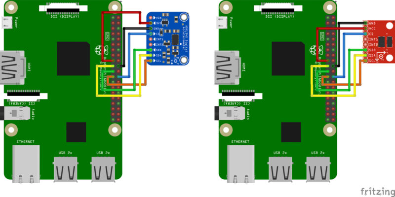
To connect the ADXL345 to the Raspberry Pi, use the wiring diagram provided above. You’ll need to connect six wires in total to ensure everything is properly connected.
2. Mount the Accelerometer
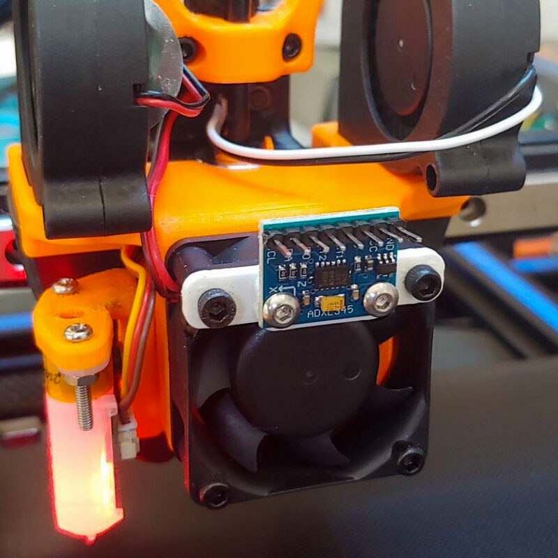
The mounting of the ADXL345 depends on the type of mount you’re using. For this guide, we’ll be using the Thingiverse mount linked above.
If you cannot find a mount for your 3D printer, you will need to find a way to temporarily attach the accelerometer to the printer. Some sticky tape or an improvised wooden mount would work if you have nothing else at hand.
However, it is important to mount the ADXL345 in a way that lines up the X and Y axes of the accelerometer with those of the printer. The circuit board of the accelerometer typically indicates which direction corresponds with which axis.
If you mount the accelerometer at a slight angle, or if you align the wrong accelerometer axis with the printer axis, your results will be compromised. So make sure to pay attention to this.
3. Install the Software
Klipper does not include the necessary software to measure resonance and tune the input shaper by default. Let’s install this software on your Klipper instance
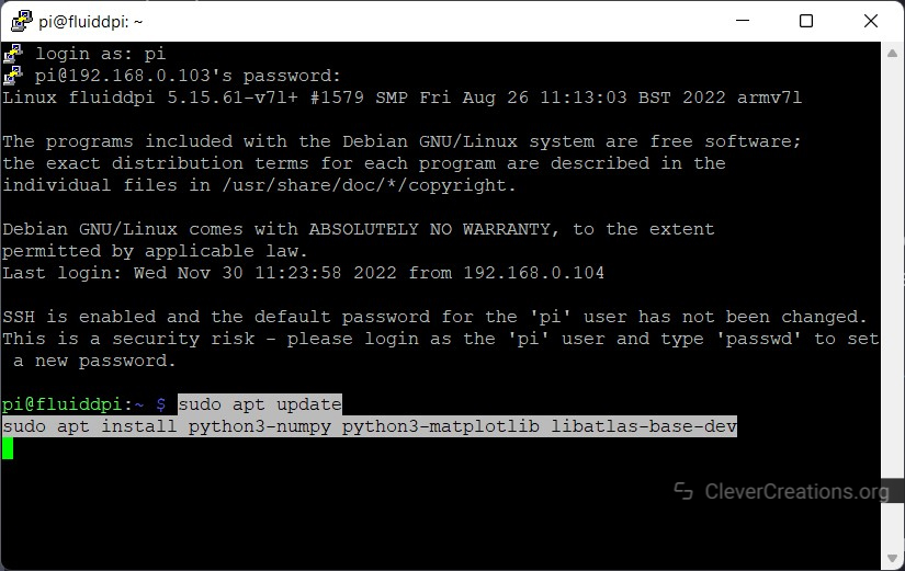
- Open PuTTY and SSH into your Raspberry Pi. Once you’ve logged in, enter the following commands:
sudo apt update
sudo apt install python3-numpy python3-matplotlib libatlas-base-dev
This command installs the Python 3 version of NumPy, Matplotlib, and the development version of the ATLAS library. After executing this command, the packages will be downloaded and installed on your system.
- Then input the following command:
~/klippy-env/bin/pip install -v numpyWith this command, you install the NumPy package into the virtual Klipper environment located on your Raspberry Pi.
Depending on the version of your Raspberry Pi, this step can take a while to complete. We recommend waiting at least 15-20 minutes for the entire process to finish. Once you get a successful installation message, you can move on to the next step.
4. Configuring the ADXL345 with the Raspberry Pi
We’ve wired the accelerometer and mounted it to the printer, now it’s time to set it up in the Klipper firmware.
Enabling the SPI Interface
We’ve wired the ADXL345 in Serial Peripheral Interface (SPI) interface mode. To use it, we need to enable the SPI interface on the Raspberry Pi.
- Input this command your PuTTY terminal:
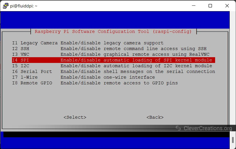
sudo raspi-config - Select Interface Options in the new window.
- Select the SPI option.
- Enable the SPI interface by clicking selecting Yes.
- Close the interface window.
Using the Raspberry Pi as a second MCU
Klipper allows you to connect multiple controllers to your 3D printer. This feature is highly useful as it allows you to expand the functionalities of your printer through the use of these additional controllers.
For instance, if you want to add more than one extruder and hot end to your printer, you can connect a different controller board to each extruder setup with the Pi. You’ll have more command over each extruder and less hassle setting up separate configurations for each extrusion’s hot end.
One popular example of this is the new Prusa MK4‘s use of a separate breakout board. This board is tailored to the print head and makes it simple to switch out or upgrade the hot end parts.
We’ll be using this feature of Klipper and configure the Raspberry Pi as an additional controller.
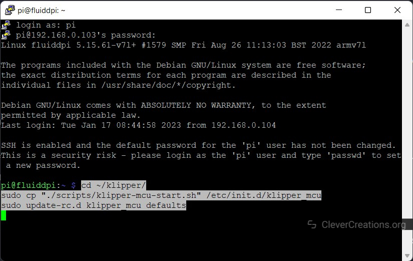
- Input and execute the following commands in your PuTTY terminal, one after another.
cd ~/klipper/ sudo cp "./scripts/klipper-mcu-start.sh" /etc/init.d/klipper_mcu sudo update-rc.d klipper_mcu defaults - Wait for these operations to finish and then input the next commands.
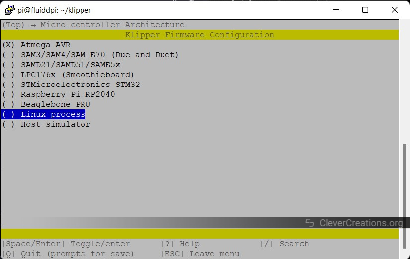
cd ~/klipper/ make menuconfig - Select the microcontroller process as Linux in the window and press Q to save and exit.

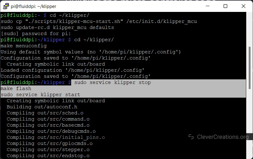
- Input the following commands in the PuTTY terminal. These commands will stop the Klipper firmware, flash the Linux microcontroller code onto the RPi, and then start the Klipper service again after the flashing process is completed.
sudo service klipper stop make flash sudo service klipper start - To avoid any permission issues from popping up, execute the following command:
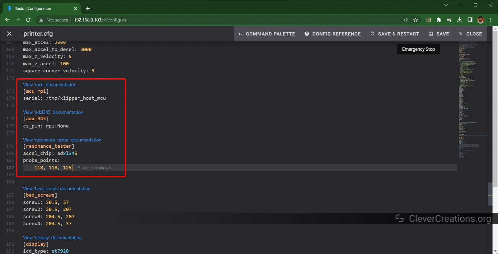
sudo usermod -a -G tty pi - Copy the following commands to the printer.cfg file in your Fluidd or Mainsail interface. Edit the X, Y, and Z probe points such that the hot end and the print bed remain at the center of the print bed.

[mcu rpi]
serial: /tmp/klipper_host_mcu

[adxl345]
cs_pin: rpi:None

[resonance_tester]
accel_chip: adxl345
probe_points:
    100,100,20  # an example
You’ve now successfully set up the ADXL345 with Klipper and Raspberry Pi! We can now begin configuring the Input shaper calibration.
5. Measuring Resonances
This is the step where we measure the 3D printer’s resonances using the accelerometer. We’ll use the readings from this step to set the input shaper values.
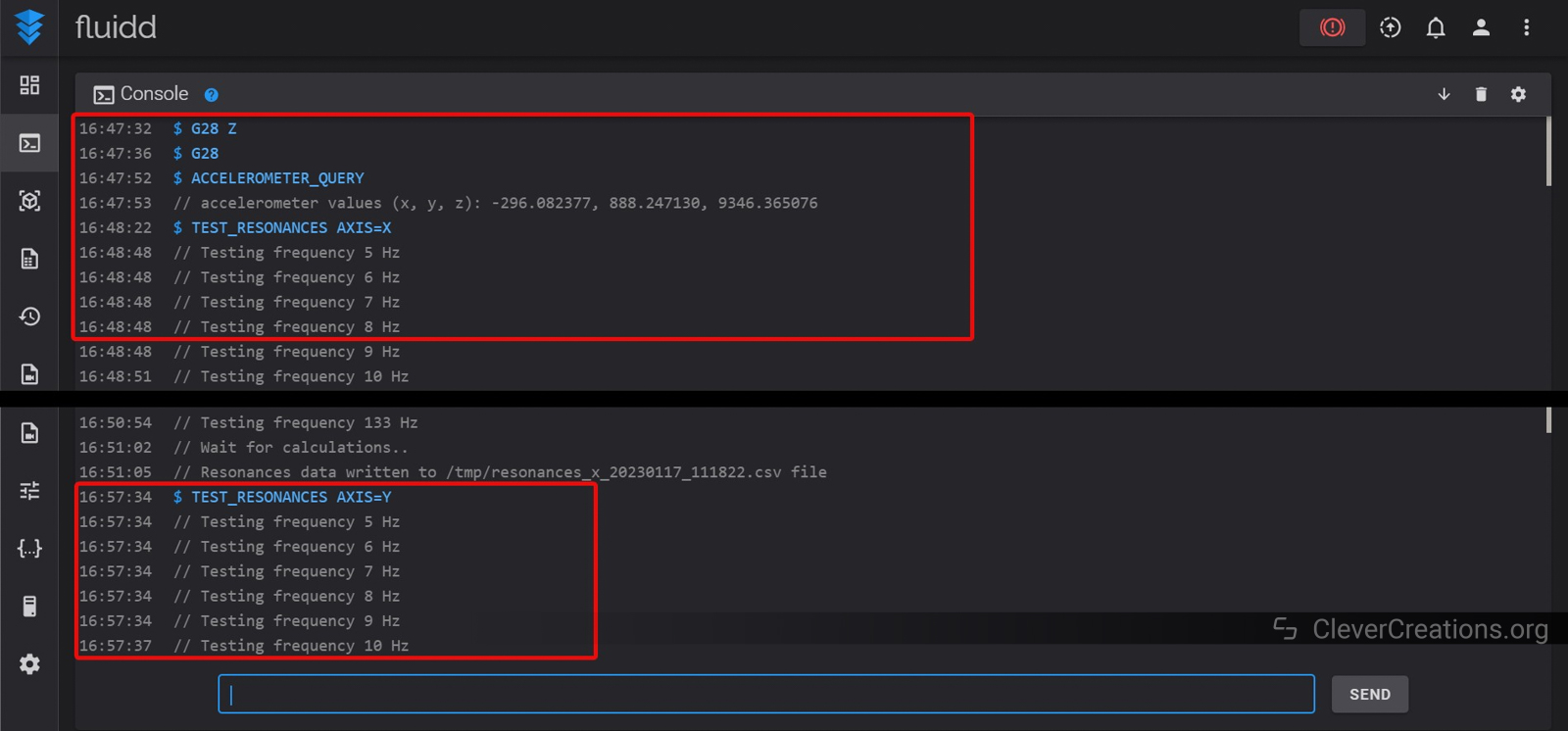
- With the accelerometer mounted on the X-axis carriage/hotend, input the following command in the Mainsail/Fluidd’s Gcode terminal:
TEST_RESONANCES AXIS=XYou’ll notice the hot end vibrating quite fast during the test. Klipper’s terminal will show the various frequencies for which we’re testing the resonance.
- Once the X-axis test is complete, move on to the Y-axis. Mount the accelerometer on the print bed and input the following command.
TEST_RESONANCES AXIS=YSimilar to the hot end vibrating, this command will cause the print bed to shake. Once the vibrations stop, the input shaper test is complete.
These tests will generate a CSV (Comma-separated values) file containing all the test data. We’ll use these files to configure our input shaper settings.
6. Getting the Test Results
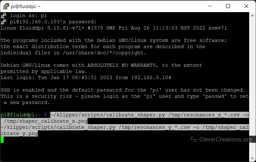
- Open PuTTY and input the following commands:

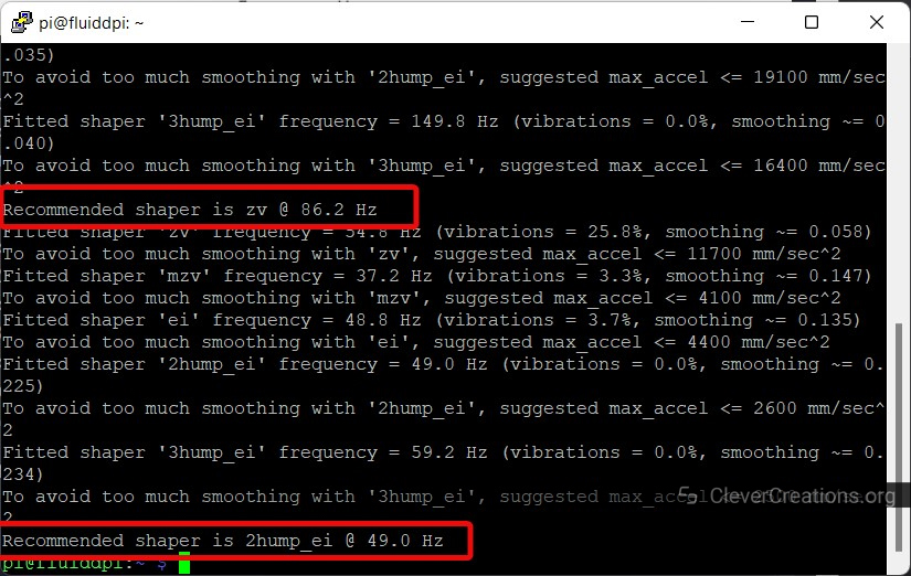
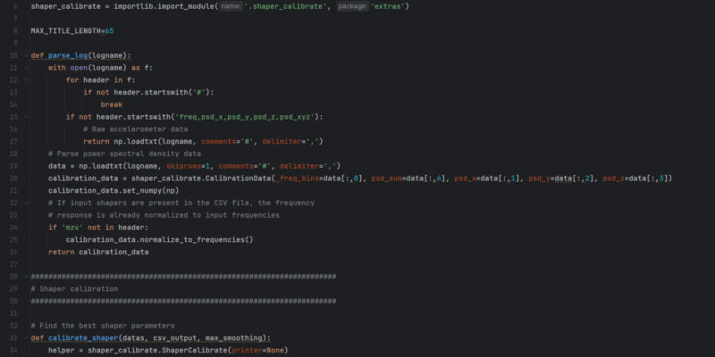
~/klipper/scripts/calibrate_shaper.py /tmp/resonances_x_*.csv -o /tmp/shaper_calibrate_x.png
~/klipper/scripts/calibrate_shaper.py /tmp/resonances_y_*.csv -o /tmp/shaper_calibrate_y.png
These commands take the CSV file generated during the input shaper test and convert it to an easy-to-understand image. Additionally, you’ll get the suggested frequencies for each input shaper and the type of input shaper that’s best suited for your 3D printer.
At this point, you can directly use the suggested values for your input shaping settings. The images are more of a visual representation of the test. If you don’t want the images, you can skip the next step.
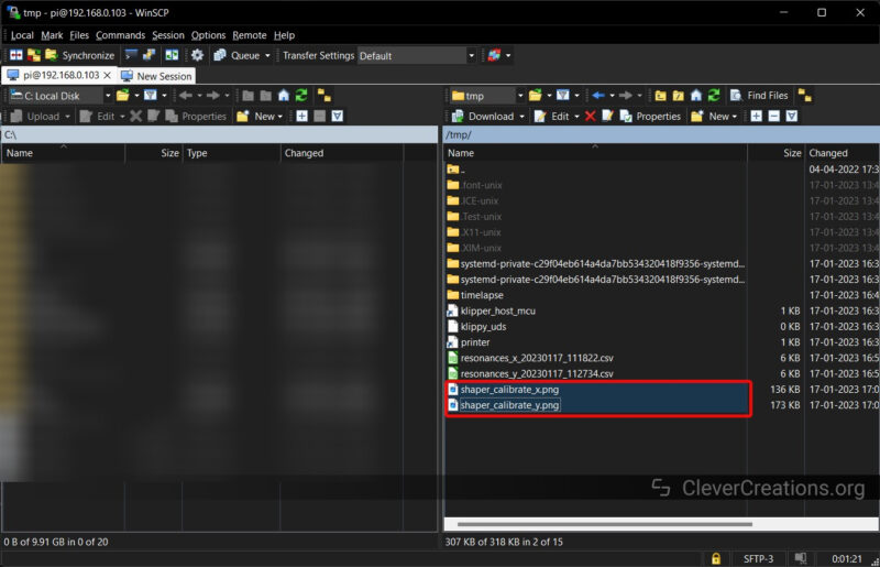
- Extract the Images using WinSCP. Locate the tmp folder inside the root directory and download the two images labeled as shaper_calibrate for X and Y.

You can use these images to understand more about the accelerometer test that we just performed. This video by 3D Printers & a Whiteboard explains the graphs in detail.
7. Setting the Input Shaper Values in Klipper
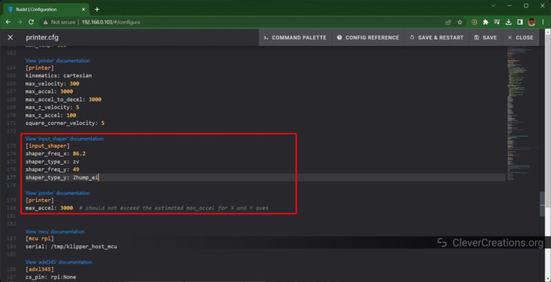
- Open the printer.cfg file and add the following section with your input shaper values and type for each axis
[input_shaper] shaper_freq_x: ... shaper_type_x: ... shaper_freq_y: ... shaper_type_y: ... [printer] max_accel: 3000 # should not exceed the estimated max_accel for X and Y axes - Save and restart the firmware.
That’s it. Your Klipper 3D printer is now configured with the correct input shaping values that were measured with the accelerometer. You’ll now notice a significant difference in your print quality at high speeds, try it out!
How Do You Use Other Accelerometers?
Klipper is compatible with more accelerometers than just the ADXL345. Some examples of supported accelerometers include the LIS2DW board, as well as the MPU-9255, MPU-6515, MPU-6050, and MPU-6500 models.
If you’re using an MPU accelerometer that communicates via the Inter-Integrated Circuit (I2C) interface, you will need to enable the I2C interface option when setting up the accelerometer with the Raspberry Pi. Please refer to the SPI configuration step above for guidance.
Conclusion: Is it Worth Using an ADXL345 with Klipper?
Though it may seem challenging at first, using an accelerometer, like the ADXL345, for input shaping on Klipper is a manageable task. By breaking the process down into smaller steps and following this guide closely, you will be able to configure your input shaper settings successfully.
The print quality you get is worth the effort you put in. Plus, the process is easy to repeat in case you ever need to tune the input shaper once again. Klipper’s documentation is also available for reference, although it can be overwhelming if you’re not familiar with the basics.
We would love to hear about your experiences with Input shaping on Klipper. If we missed any steps or if you need more information, please don’t hesitate to leave a comment below.


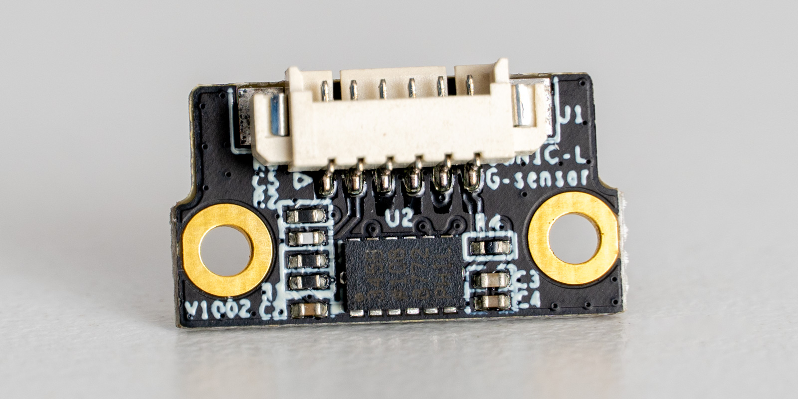
hi. I think first photo is Creality ADXL345? can you make some additional photos in other views? you have USB-C or 5-ping rounded connector on this accelerometer board?