
Klipper’s input shaping is one feature that we can’t get enough of. It reduces the ringing and ghosting artifacts that occur when you print fast. No matter the print speed, it’s something that gives 3D prints smoother surfaces and reduced surface artifacts. Who doesn’t want that?
However, by default Klipper does not have the input shaper enabled. And, just like Pressure Advance, you’ll still need to calibrate its settings for your particular 3D printer. The input shaper calibration process is quite elaborate, and it’s something you want to get right.
To help you with that, this article covers the ins and outs of input shaping in Klipper. After reading and going through the steps, your 3D printer will deliver you impressive results at high print speeds.
Let’s start shaping!
What is Klipper Input Shaping?
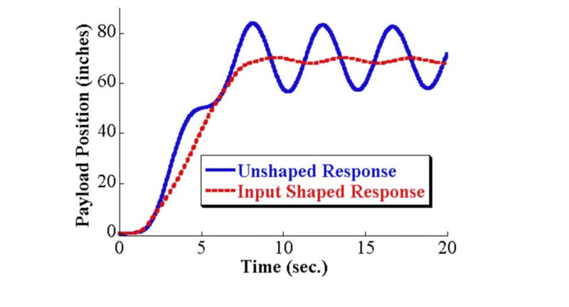
Klipper’s input shaping is a feature that reduces unwanted vibrations produced in the printer. It fine-tunes the motion of the hot end and the print bed such that there’s little to no resonance during 3D printing.
These vibrations are more pronounced when you’re printing at fast speeds with high acceleration rates. You might’ve noticed the printer’s frame shaking when the print head moves quite fast.
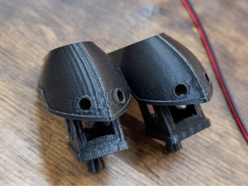
No matter how rigid your printer frame is, these vibrations will show up in your prints. The ringing or ghosting artifacts that you might have heard about are a direct by-product of these high-frequency vibrations.
Why Do You Need Input Shaping?
The main reason to enable input shaping is to achieve high-quality print results at high printing speeds. The ringing that occurs when you print fast affects the visible appearance of the 3D print. Especially if you’re printing an aesthetic model where visual features are essential, input shaping comes in quite handy.
A similar benefit of input shaping is the ability to print at higher speeds without compromising print quality. This helps you save time by reducing print times, allowing you to focus on other essential tasks. For 3D printing businesses, this can significantly increase the bottom line.
How Does Input Shaping Work?
Input shaping works by finely tuning the signals that are sent to the 3D printer’s stepper motors. It mixes the input signals such that one signal tells the stepper motor to move while the following one cancels out the vibration that might be produced with this stepper motor’s movements.
To control the intensity, interval, and effects of these input signals, there are a few algorithms that are known as Input shapers. These input shapers fine-tune the input signal such that it does not affect the printer’s accuracy and quality but still effectively reduces the vibrations.
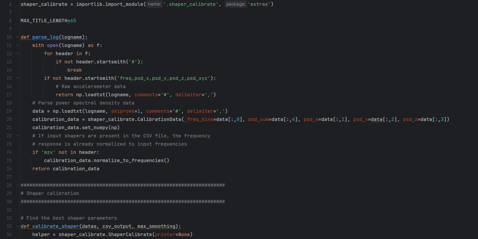
The math behind all of this is pretty complex and falls outside the scope of this article. There’s a detailed research paper that goes over the algorithms of Input shaping. It’s worth reading if you want to get into the nitty-gritty of things.
What Is Resonance Compensation?
Resonance compensation is a technique of identifying and mitigating the natural frequencies or resonances in a mechanical system. It’s essentially the same concept as input shaping, albeit with a different terminology.
In 3D printing, resonance compensation involves analyzing the printer’s movements to identify the frequencies at which the vibrations are most pronounced. Once Klipper determines these resonant frequencies, it can use input shaping algorithms to cancel out the printer’s vibrations.
In other words, resonance compensation is the fundamental principle of input shaping. When someone tunes their printer for resonance compensation, they’re essentially adjusting the input shaping settings to counteract the negative effects of resonances on print quality.
Therefore, although the terminology may vary, the underlying principle and goal remain the same: to achieve smoother, higher-quality prints by accurately modifying movement commands that address mechanical vibrations.
How to Configure Input Shaping in Klipper
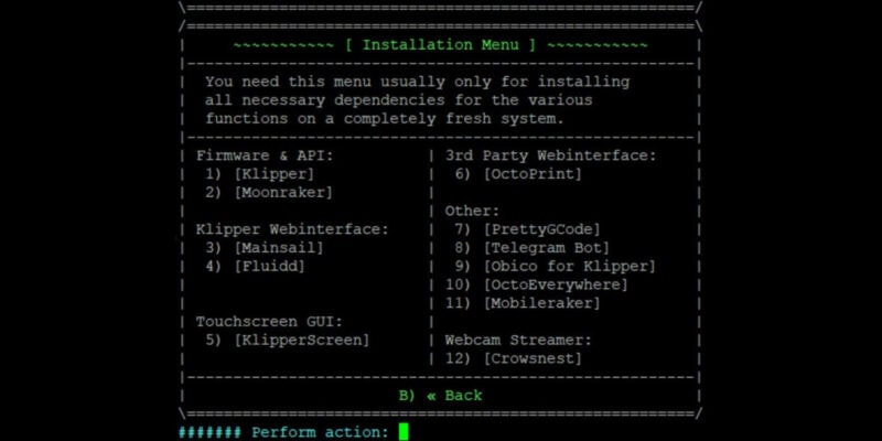
There are two methods for configuring Klipper input shaping – one is the manual method, and the other involves using an accelerometer. We’ve covered how to configure input shaping in Klipper with an ADXL345 accelerometer in a separate post to keep things more organized.
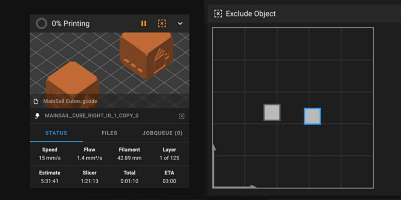
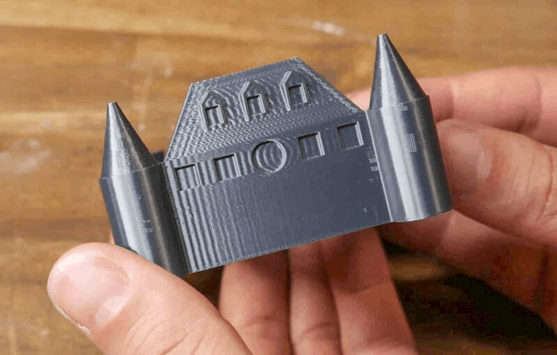
In this article, we will focus on the manual input shaper method. This method uses a tuning tower to highlight the ringing artifacts at fast print speeds. The tuning tower is an L-shaped model with one wall representing the vibrations of the X-axis while the other wall represents the vibrations of the Y-axis.
By taking resonance measurements on the tuning tower after printing, you can make precise adjustments to the Klipper configuration to reduce or eliminate those ringing artifacts. This manual resonance testing method allows you to fine-tune your printer’s performance without the need for additional hardware like an accelerometer.
While the manual method can be more accessible and cost-effective for many 3D printing enthusiasts, it does require a keen eye and some patience. The key is to observe the results of your tuning tower print closely, noting any imperfections and adjusting the Klipper input shaping parameters accordingly.
Now let’s get started!
Configuring Slicer Settings
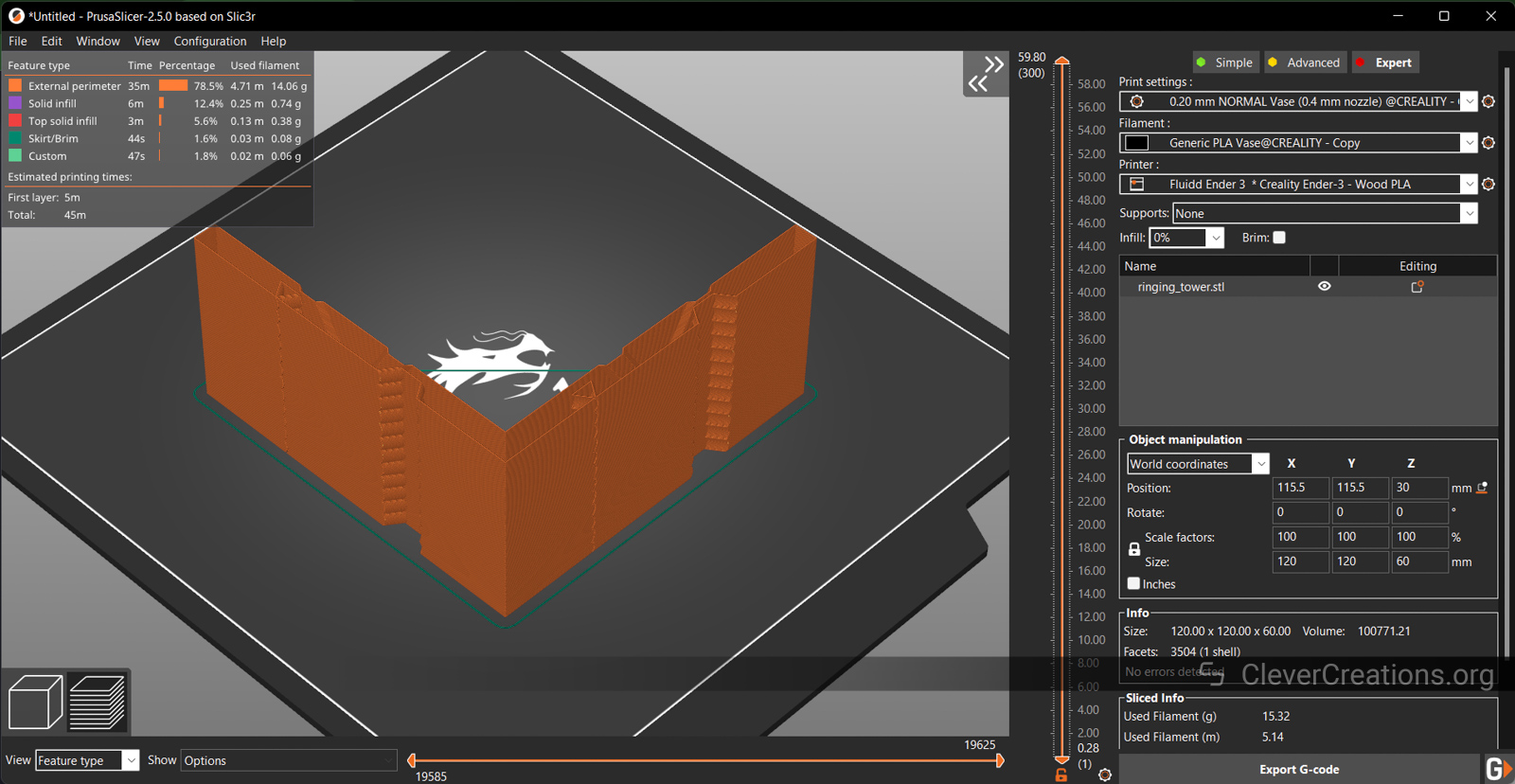
Start by loading the tuning tower into your slicer. After this, set the following slicer settings for the tuning tower to work as designed. It’s important to not deviate from these settings, as this will negatively affect your input shaping results.
- The layer height should be between 0.2-0.25 mm.
- Zero infill and zero top layers.
- Perimeters or Wall count should be at max 2 with a base height of 2 mm. Alternatively, you can use Vase mode for better results.
- Print speeds should be between 80-120 mm/s. The faster it is, the more pronounced the vibrations will be.
- A minimum layer time of max. 3 seconds. Any higher and it slows down the print speed, which affects the entire test.
- Disable custom or dynamic acceleration settings in the slicer. We’ll set this later using the Klipper console.
- Keep the model orientation as it loads in your slicer. Don’t change its orientation, as we’ll use its X&Y markings to identify the vibrations of the corresponding X and Y axes.
Configuring Klipper & Printing the Tuning Tower
In this step, we’ll print the tuning tower with the above slicer settings. However, we’ll first need to set up various parameters in Klipper first. We’ll do this by manually entering several commands.
- If you’ve changed the square_corner_velocity parameter, change it back to 5.0. If you haven’t made any changes or don’t know about this setting, skip this step.
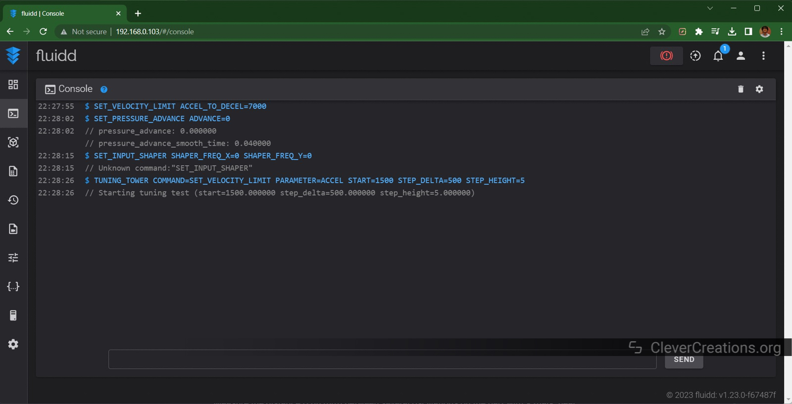
- Increase the maximum acceleration to deceleration speed for your printer. Input the following command:
SET_VELOCITY_LIMIT ACCEL_TO_DECEL=7000 - Set the Pressure advance to Zero using this command:
SET_PRESSURE_ADVANCE ADVANCE=0 - Remove any previous Input Shaper parameters by executing this command:
SET_INPUT_SHAPER SHAPER_FREQ_X=0 SHAPER_FREQ_Y=0If an ‘Unknown command’ error pops up, you can safely skip this step. This error command indicates that there are no previous input shaper settings configured.
- Execute the command:
TUNING_TOWER COMMAND=SET_VELOCITY_LIMIT PARAMETER=ACCEL START=1500 STEP_DELTA=500 STEP_HEIGHT=5This command instructs the printer to increase the acceleration by mm/s2 every 5 mm. The printer starts the print with a mm/s2 acceleration rate and will end the tuning tower test with a 7000 mm/s2 value. Higher acceleration speeds help to make the ringing effect more prominent.
- Slice the model using the above slicer settings and print it.
Measuring Ringing Frequency
Klipper’s Input shaper needs to know the main ringing frequencies of your Klipper 3D printer to compensate for it. To do so, we will use the tuning tower you printed earlier to measure the distance between the ghosting artifacts. This will allow us to accurately determine these frequencies.
- Use the X and Y markings on the tuning tower to recognize the ringing frequency response on the X and Y axes respectively.
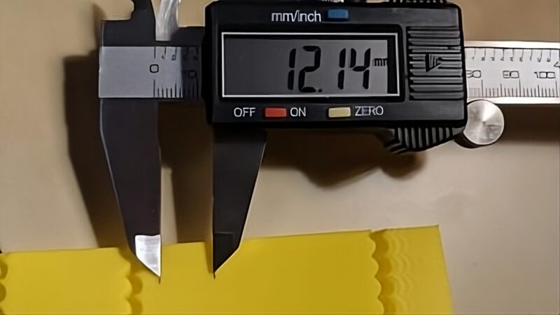
- Take a vernier caliper or a scale ruler and measure the distance between multiple oscillations on the X-axis. Preferably skip the first couple of ringing marks and measure the distance across 6 to 10 oscillations. Mark this distance using a Sharpie marker.
- The formula for the ringing frequency of the X axis is V · N / D (Hz).
- V denotes the velocity (print speed) for outer perimeters in mm/s.
- N is the number of oscillations
- D stands for the distance between the oscillations.
If you’ve marked 6 oscillations with a distance of 10 mm between them, and you printed at 100 mm/s, the ringing frequency for the X-axis is 100 * 6 / 10 ≈ 60 Hz. Write this number down.
- Repeat the above steps for the Y axis.
Setting Input Shaper in Klipper
Here, we input the values from the previous ringing frequency test in our Klipper printer configuration file. This way, Klipper knows the ringing frequencies of your 3D printer and can apply the correct input shaper settings from now on.
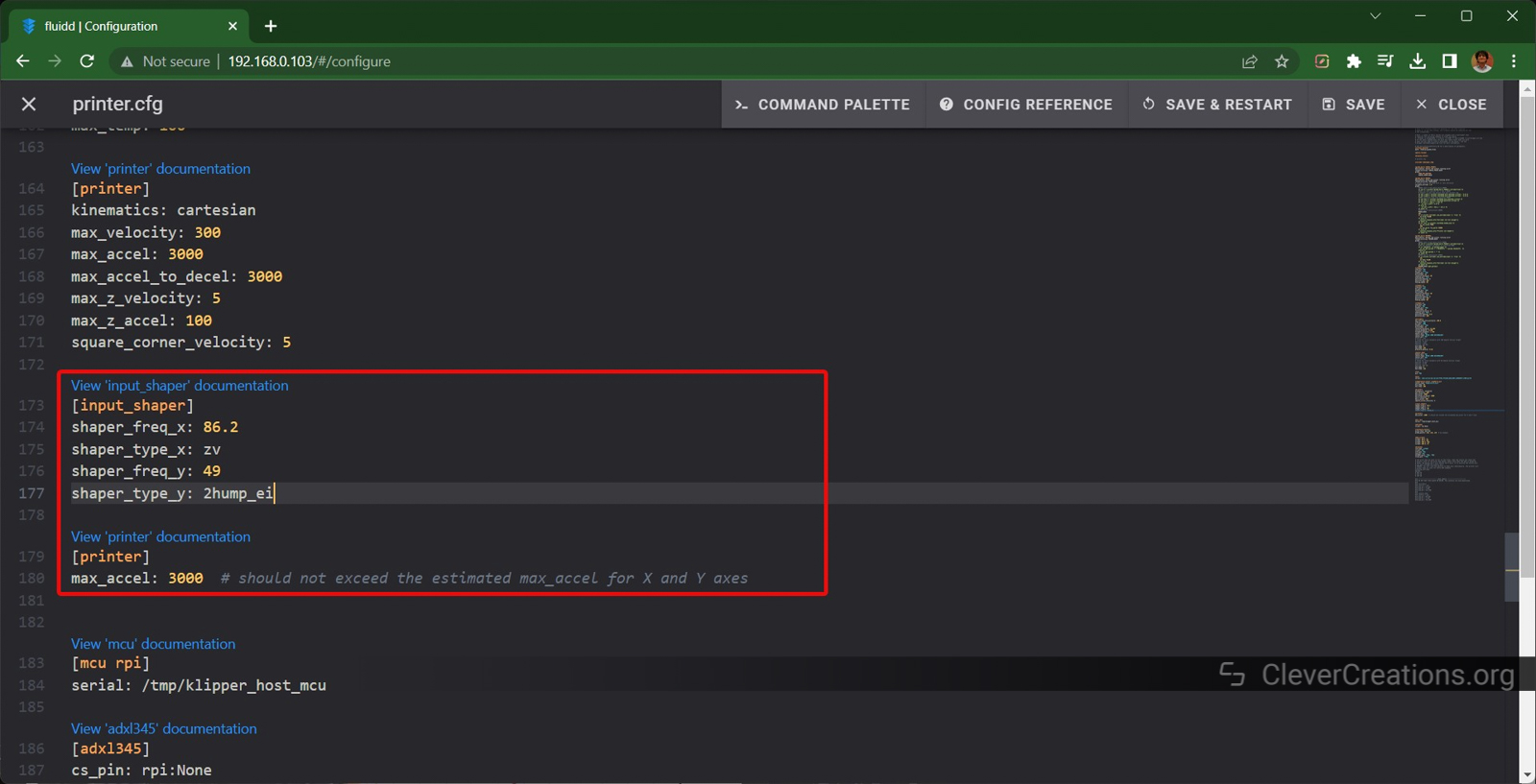
- Open the printer.cfg file on your Klipper web interface
- Add the following section:
[input_shaper] shaper_freq_x: 60 # frequency for the X mark of the test model shaper_freq_y: ... # frequency for the Y mark of the test model - Input the individual frequencies you got from the above calculations in this section.
- Save the file and restart the firmware.
Input Shaper Configuration
After the resonance test, the next step is to choose the type of input shaper you want to use. The input shaper plays a crucial role in detecting the printer’s resonance frequencies and ensuring smooth printing.
Klipper supports four types of Input shapers – MZV, EI, 2HUMP_EI, and 3HUMP_EI. The last two are configured for different configurations and aren’t typically used for most printers. We’ll be configuring the printer with the MZV or EI input shaper for this step.
- Execute the following commands in the Klipper’s Gcode window one after the other.
SET_VELOCITY_LIMIT ACCEL_TO_DECEL=7000 SET_PRESSURE_ADVANCE ADVANCE=0 SET_INPUT_SHAPER SHAPER_TYPE=MZV TUNING_TOWER COMMAND=SET_VELOCITY_LIMIT PARAMETER=ACCEL START=1500 STEP_DELTA=500 STEP_HEIGHT=5 - Print the sliced tuning tower again.
- Restart the firmware and input the above commands once again into the Gcode terminal but change the input shaper type. You can do this with the following command:
SET_INPUT_SHAPER SHAPER_TYPE=EIPrint the tuning tower with the EI input shaper again.
- Compare the two prints with the EI and MZV input shapers. Choose the one that shows better print results. Look for the model with less ringing but with sharp corners.
- Add shaper_type: mzv or shaper_type: ei to the [input_shaper] section in your printer.cfg file.
[input_shaper]
shaper_freq_x: 60
shaper_freq_y: ...
shaper_type: mzv
Congrats! You have now configured input shaping with Klipper and selected the best input shaper.
Setting the Maximum Acceleration
Input shapers like the EI and MZV algorithms mentioned above are used to smooth out the vibrations that occur at extremely high speeds. However, if the maximum acceleration is set too high, input shaping can overcompensate. This causes excessive smoothing and rounding in your printed parts, with less detail as a result.
Therefore, we need to adjust the maximum acceleration speeds in Klipper to ensure minimal artifacts and high precision in your printed parts.
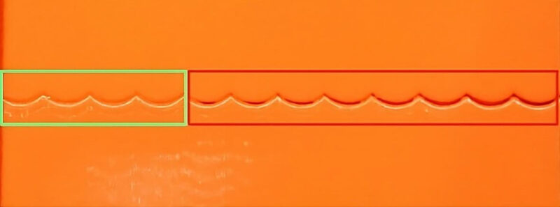
- In the tuning tower that you printed for the MZV or EI input shaper test, there’s a small wall gap of ~0.15 mm.
- Check the gap where it just starts to widen. The model starts with 1500 mm/s2 acceleration and increases it by 500 mm/s2 at every 5 mm interval.In the (90-degree rotated) image above, you can notice the gap widens at approximately 20-25 mm in height. This indicates that the best acceleration settings would be between 3000-3500 mm/s2.
- Take the minimum of the two acceleration values, i.e. 3000 mm/s2.
- Open the printer.cfg file and add the command – max_accel: 3000 under the printer section.
- Save and restart Klipper.
That’s it! You should now see a significant difference in the print quality when you print at high speeds.
Which Shaper Algorithm is Best?
The best input shaper algorithm in Klipper depends on the 3D printer and print settings you’re using. There’s not a one-size-fits-all answer.
For the best results, print the tuning towers with maximum acceleration four times, all with different input shaper algorithms. That way, you can compare them and pick the one that looks best for your specific setup.
Then, choose the best input shaper parameters that allow you to print with maximum acceleration speeds and don’t smooth out the edges too much. The focus should be on balancing the print speed with print quality.
Klipper claims that the EI input shaper algorithm works best for bed slinger printers such as the Ender 3 and Prusa. But, in our case, when we tested out the resonant frequencies using an accelerometer, the suggested input shapers were the ZV and 2HUMP_EI algorithms.
In short, try out all four input shaper types and select the one that gives you the best print results.
Does Input Shaping Increase Print Speed?
Input shaping does not directly increase print speed. However, it gives you the option to increase your printing speeds beyond what you would normally achieve, without losing print quality.
One of the main factors that limit print speeds is the vibrations that occur when printing at high speeds. Because input shaping cancels out these vibrations, you can print faster at higher print speeds, or get better print quality at identical print speeds.
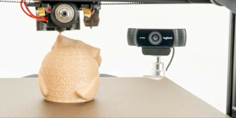
Do You Need an Accelerometer for Input Shaping?
An accelerometer is not strictly necessary for input shaping. By using the tuning tower method, you can avoid having to use any additional hardware. However, it’s still a good idea to use an accelerometer at some point. It’s more precise, faster, and removes the need for human interpretation of the results.
Conclusion
In summary, Klipper’s input shaping is quite effective at what it does. By canceling out the printer’s resonant frequencies, it lets you print faster without compromising on print quality.
Unlike when using an accelerometer, you don’t need any additional equipment when manually tuning the input shaper settings. It might take an hour or two to print, measure, test, and configure everything in your Klipper configuration, but the outcome is all worth it.
By following this input shaper tuning guide carefully, you can save a lot of time and effort that would otherwise go into researching and experimenting with input shaping settings.
In case you bump into any issues during the process or you think we’ve missed something, feel free to reach out to us; we’d be glad to help.