
The Duet Wifi is a control board from Duet3D for 3D printers, laser engravers, and home CNC machines. I have been using it for my new 3D printer and have been happy with its features and performance so far.
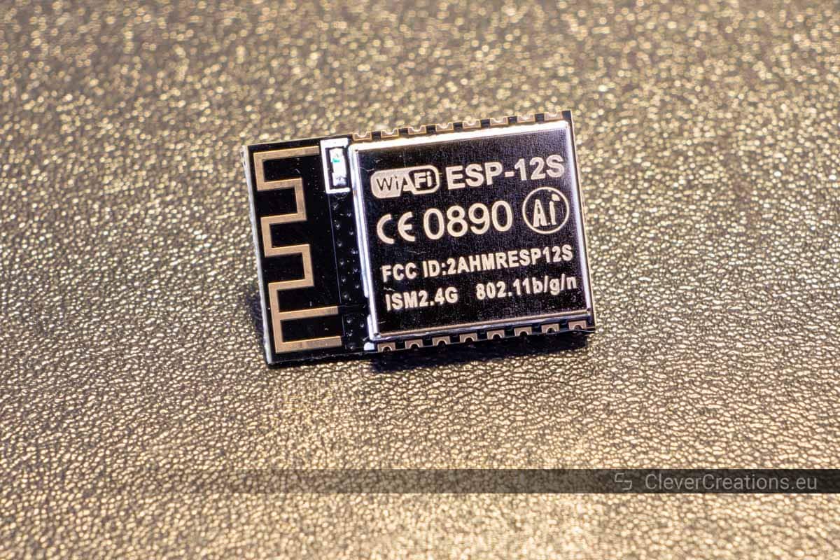
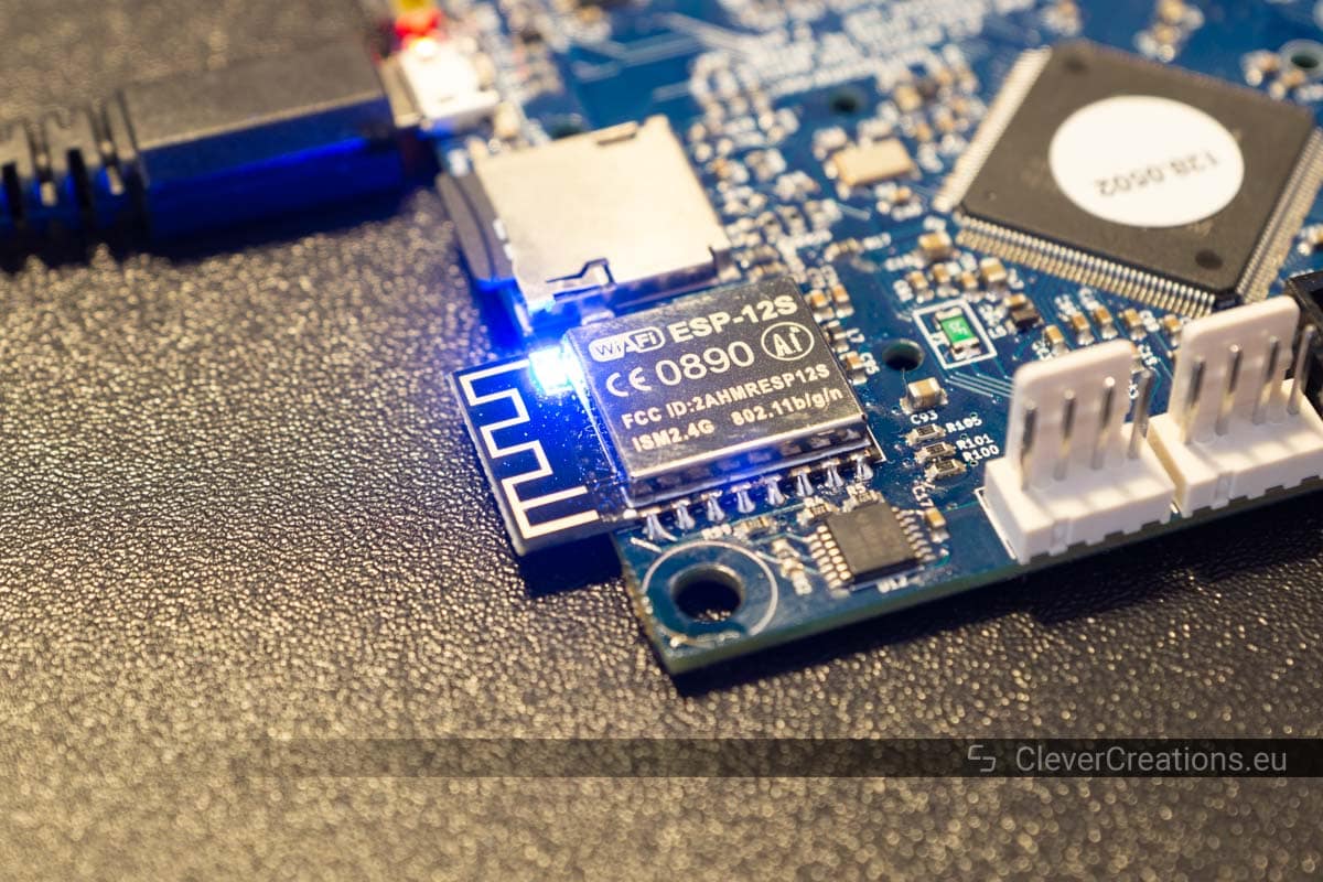
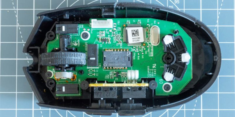
Unfortunately, I ran into an issue where I suddenly could not connect to the board over Wifi anymore. After troubleshooting the connection problems, it turned out that the ESP-12S wireless module on the Duet had broken.
I did not want to pay another ~$200 for a replacement control board (especially knowing that it can just break like that), so I was a bit desperate to find a solution. Luckily it was possible to desolder and replace the broken ESP-12S module on the circuit board. With a couple of soldering tools and a bit of patience, this solved the problem.
In this article I will guide you through the steps of replacing the Wifi module. You can follow them to repair a defective ESP-12S or ESP-07S on a Duet 2 Wifi, but also to replace different ESP8266-based Wifi modules on other circuit boards.
Troubleshooting the Duet WiFi Connection and Diagnosing the Problem
Replacing the ESP-12S module was not the first thing I tried to fix the wireless connection on the Duet 2 Wifi. I went through several other troubleshooting steps that I hoped would solve the problem. None of them did, but I will still go over them in case they are of use to you.
For context: The wireless connection on my Duet stopped working suddenly. One moment I was working on the 3D printer and everything was fine. Then I did some work on the printer that involved moving the extruder carriage by hand (more on that later). After that, the wireless connection disappeared.
These were the troubleshooting steps I took:
Resetting the Duet
Resetting the Duet with the onboard reset button was the first thing I tried. Needless to say, I still could not connect over Wifi after the board had booted up again.
Checking Whether the Duet is Connected to the Network
Maybe the problem was not with the Duet itself, but with something else along the connection path. Logging into the admin panel of the router showed that both the router and the network were fully operational, however.
What the router also told me was that the Duet was not connected to the local network at all. A good indicator that the problem was with the Duet itself.
Restarting the Wireless Module
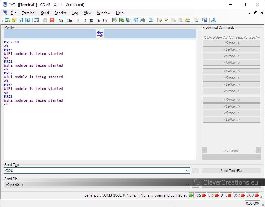
Something else I did was trying to restart the ESP-12S Wifi module by sending M552 commands (M552 S-1 followed by M552 S0 and then M552) in the YAT terminal. This gave me a persistent “WiFi module is being started” response. No matter how long I waited, the module never finished starting.
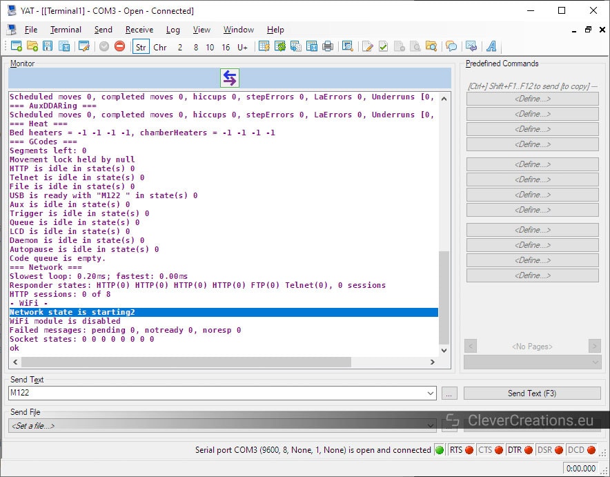
Requesting the diagnostic information with an M122 command also gave a permanent “Network state is starting” message. Not a good sign.
Creating a New Config File
At this point, I was pretty sure that there was some kind of hardware problem with the ESP-12S. But there were still a couple of things I could try.
The first thing was to generate a new config.g file. A long shot, but maybe something got corrupted in the old one. Honestly, I was grasping at straws a bit at this point.
I generated a new config file using the RepRapFirmware configuration tool and replaced the old one on the SD card, but once again without success.
Updating the Firmware
The next logical step was to update the firmware. Once again, maybe the old firmware got corrupted somehow. Worth a shot I guess.
The Duet Wifi was running on the 3.1.1 firmware release, which was already a recent version. But a 3.2 version got released a few days back, so I installed that version to see if it would fix the problem.
It did not fix the problem.
I also tried updating the firmware of the ESP-12S itself, but I could not get that to work. This made sense if the module was in fact broken.
Diagnosis
After trying all these solutions, it was clear to me that only the ESP-12S/ESP8266 module was defective. During troubleshooting, everything else on the board worked normally when I sent commands in the YAT terminal.
There are several posts on the Duet3D forums that suggest having the Duet replaced under warranty in this situation. For me this was no option, as the warranty had already expired.
Replacing the ESP-12S was something I could do, so that’s what I decided to attempt as a last resort. I was pretty confident that this would work. Even if it didn’t, spending $5 on a replacement Wifi module was not a big deal compared to spending $200 on a whole new Duet.
My best guess as to why the ESP-12S broke is that when I moved the extruder carriage by hand, the stepper motors generated back EMF (the voltage generated when a motor acts as a generator) that damaged the Wifi module. In the future, I will either use the stepper motors to move the carriage or disconnect the stepper wiring before moving things by hand.
But for now, let’s take a look at how you can replace a defective ESP8266 module!
How to Replace a Broken ESP8266 Module
You can use these steps to replace any ESP8266-based module that is soldered directly to a circuit board. Common examples are the ESP-12S, ESP-07S and ESP-13. They are all fairly similar and are typically attached to the PCB in the same way (soldered).
If you use an ESP8266 module with pin headers you can obviously just remove it from its socket and swap it out with a replacement.
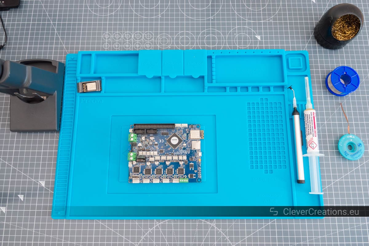
What You’ll Need
|
|
Tools | ||
|---|---|---|---|

|
Check Price | ||

|
Check Price | ||

|
Tweezers are also okay, but they are more fiddly to use for this.
|
Check Price | |

|
Strongly recommended for any (de)soldering
|
Check Price | |
|
|
Parts | ||
|---|---|---|---|
|
If you have a Duet Wifi with an ESP-12S, you can swap it out with an ESP-07S and vice versa. The ESP-07S has an external antenna that provides better Wi-Fi signal.
|
Check Price | ||
|
Check Price | ||

|
Check Price | ||

|
Check Price | ||
Desoldering
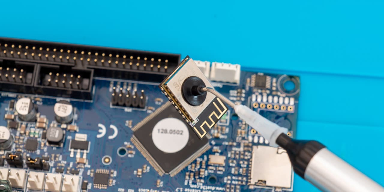
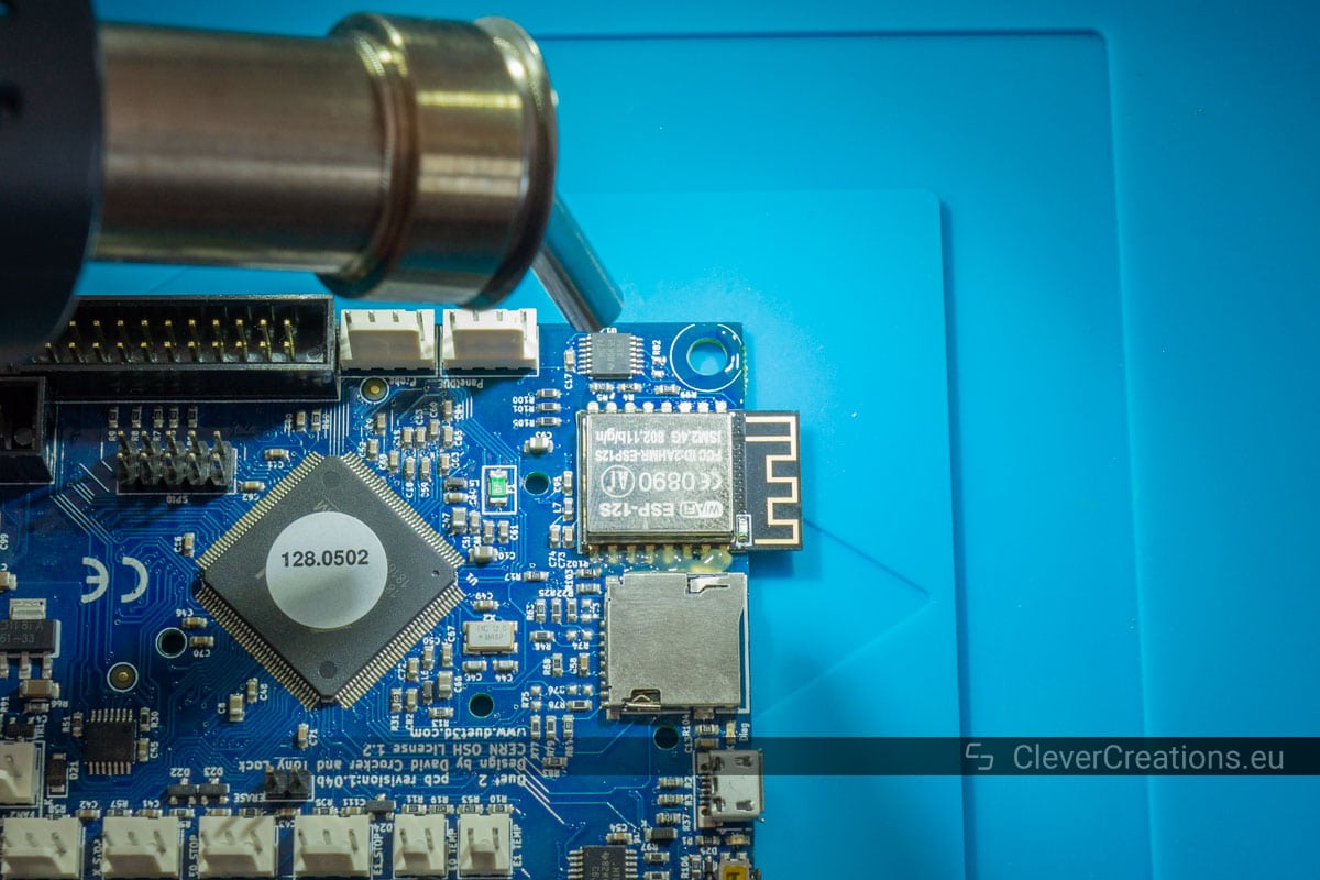
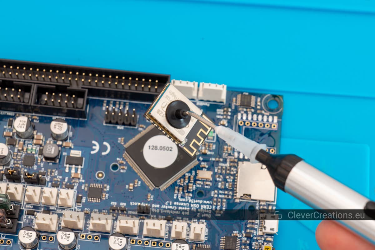
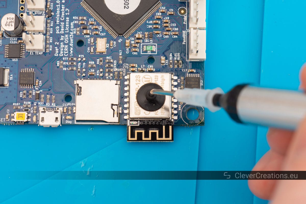
The first step in replacing the wireless module is to remove it from the circuit board. This might seem like a daunting task if you have never desoldered before, but it is fairly straightforward and I will guide you through it.
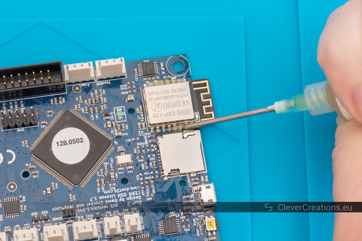

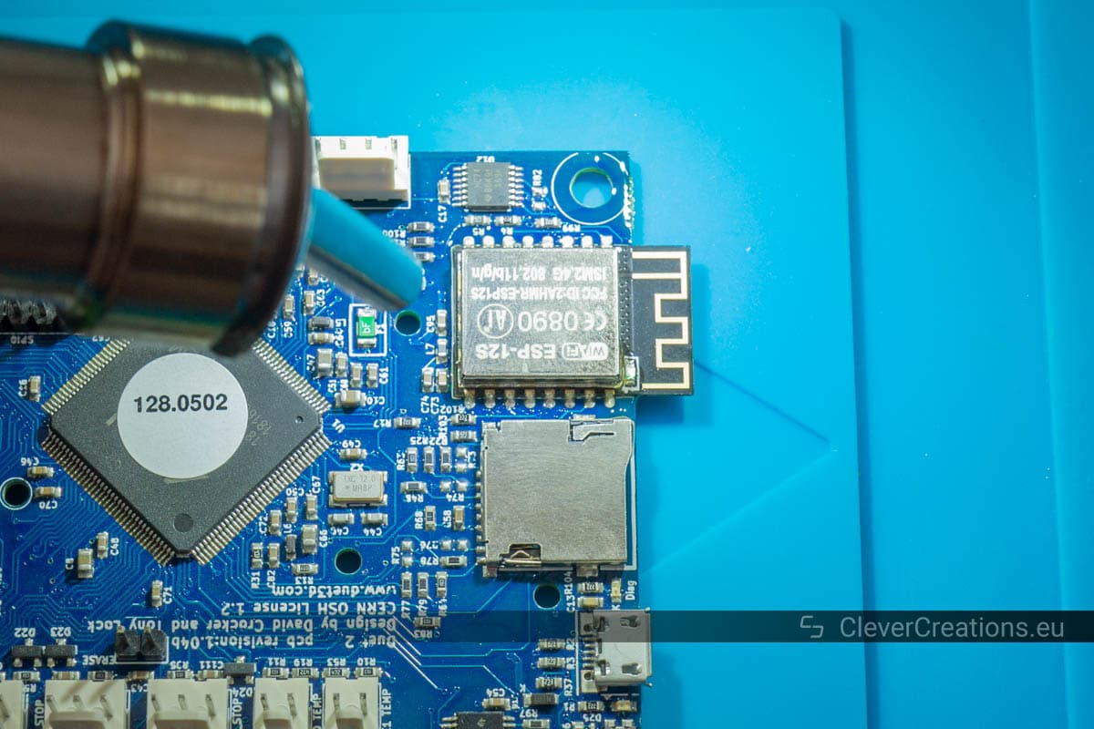

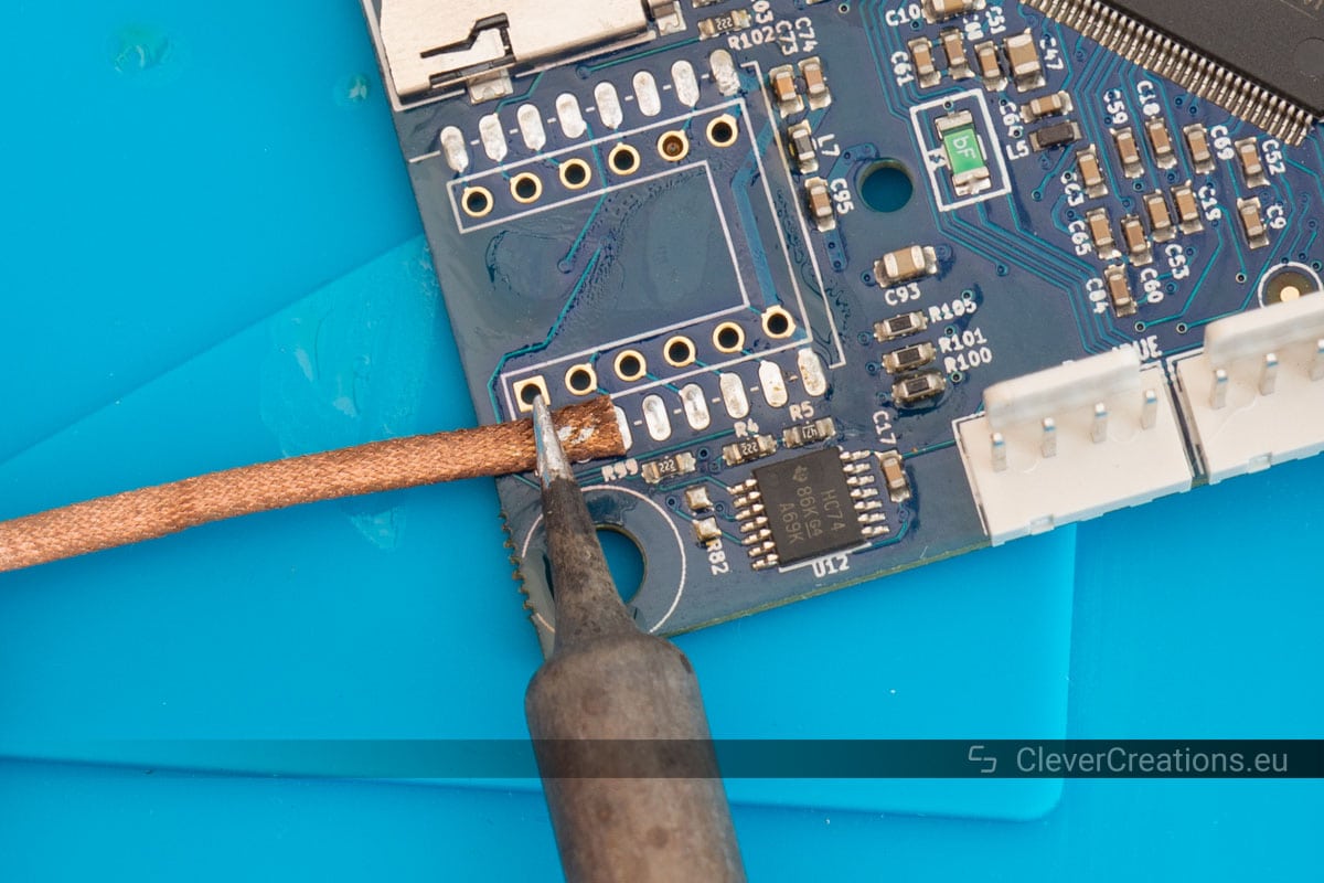
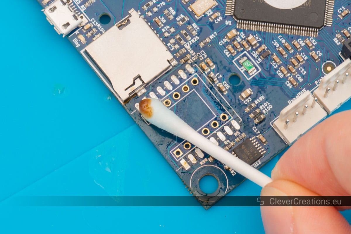
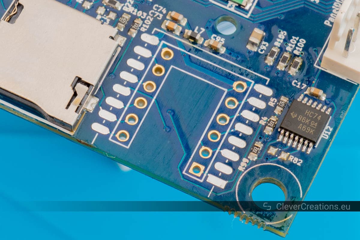
Cleaning the Solder Pads
Before soldering the new module to the board, we must first clean the solder pads. We want to create good connections and old flux and solder are not going to help with that.
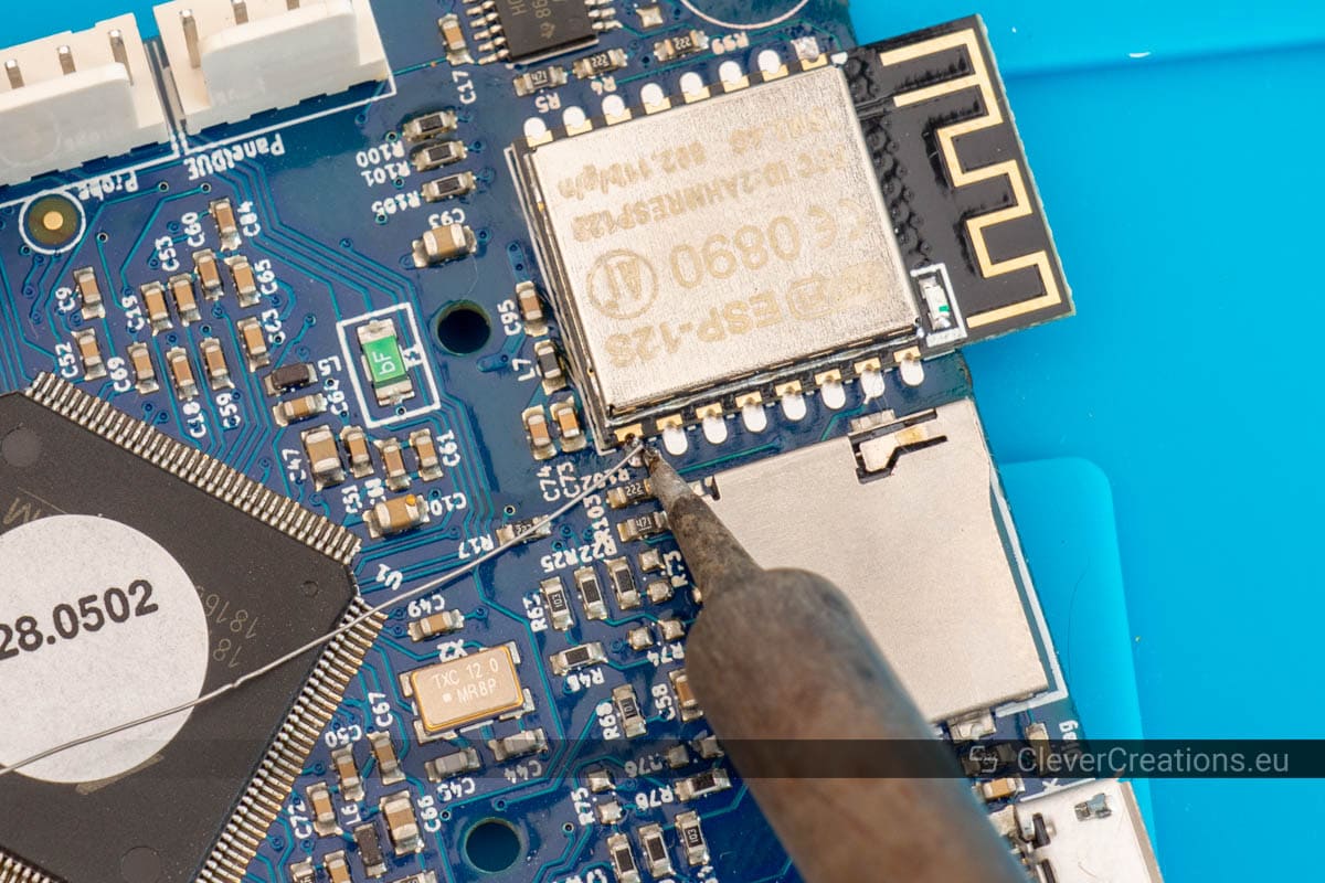
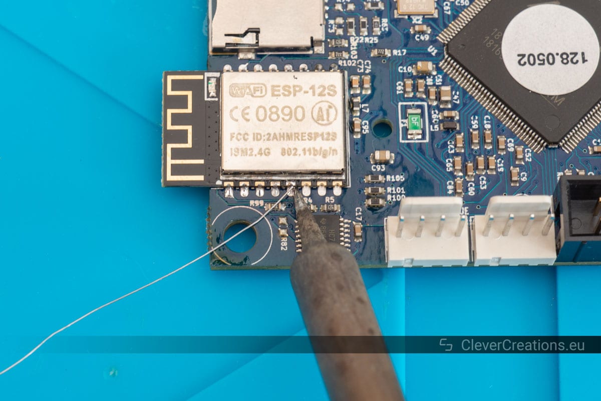
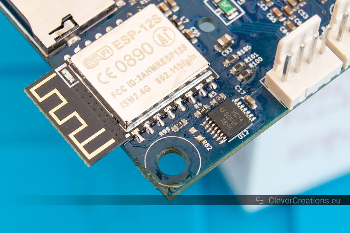
Soldering the New ESP8266 Module Onto the Circuit Board
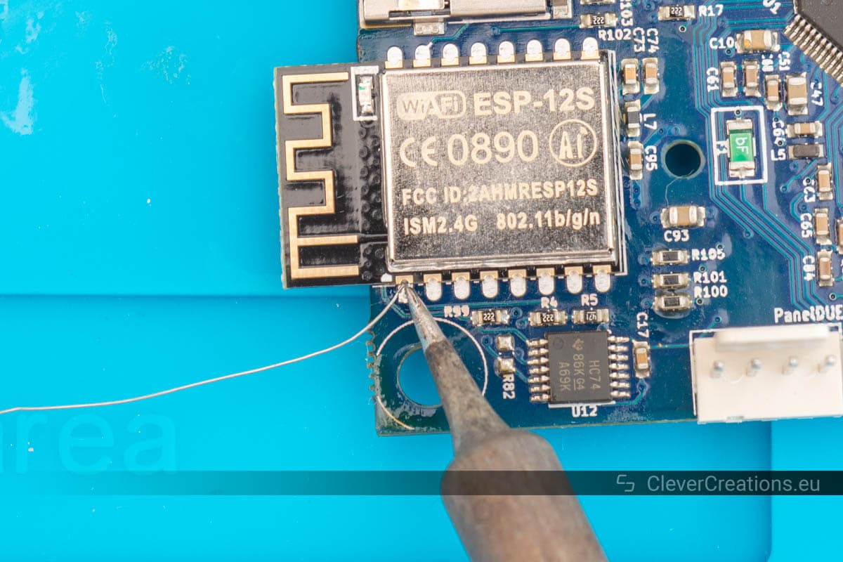
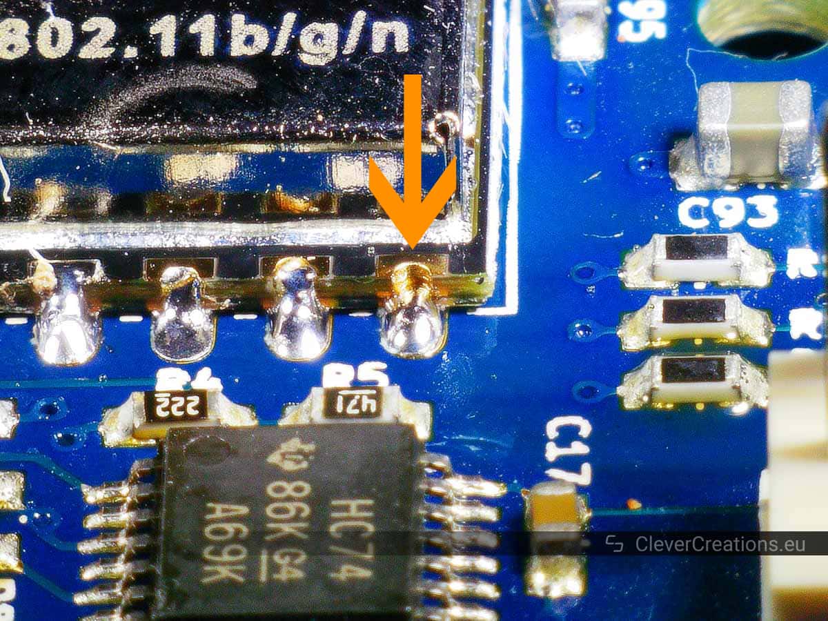
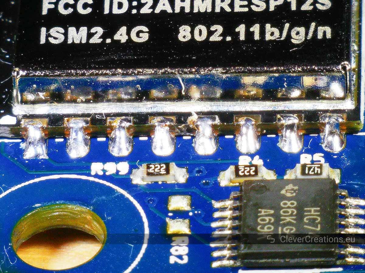
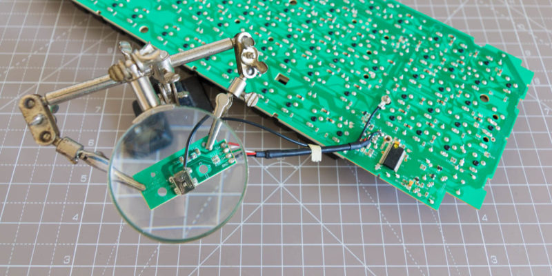
Inspecting the Solder Joints
If you have access to a microscope, you can use it to inspect the solder joints up close. But in this case you use any kind of magnification, or even do it by eye (if you have good eyes). The pins on the ESP modules are fairly large and are relatively easy to inspect compared to pins of typical SMD components.
Updating the WiFi Module Firmware & Testing
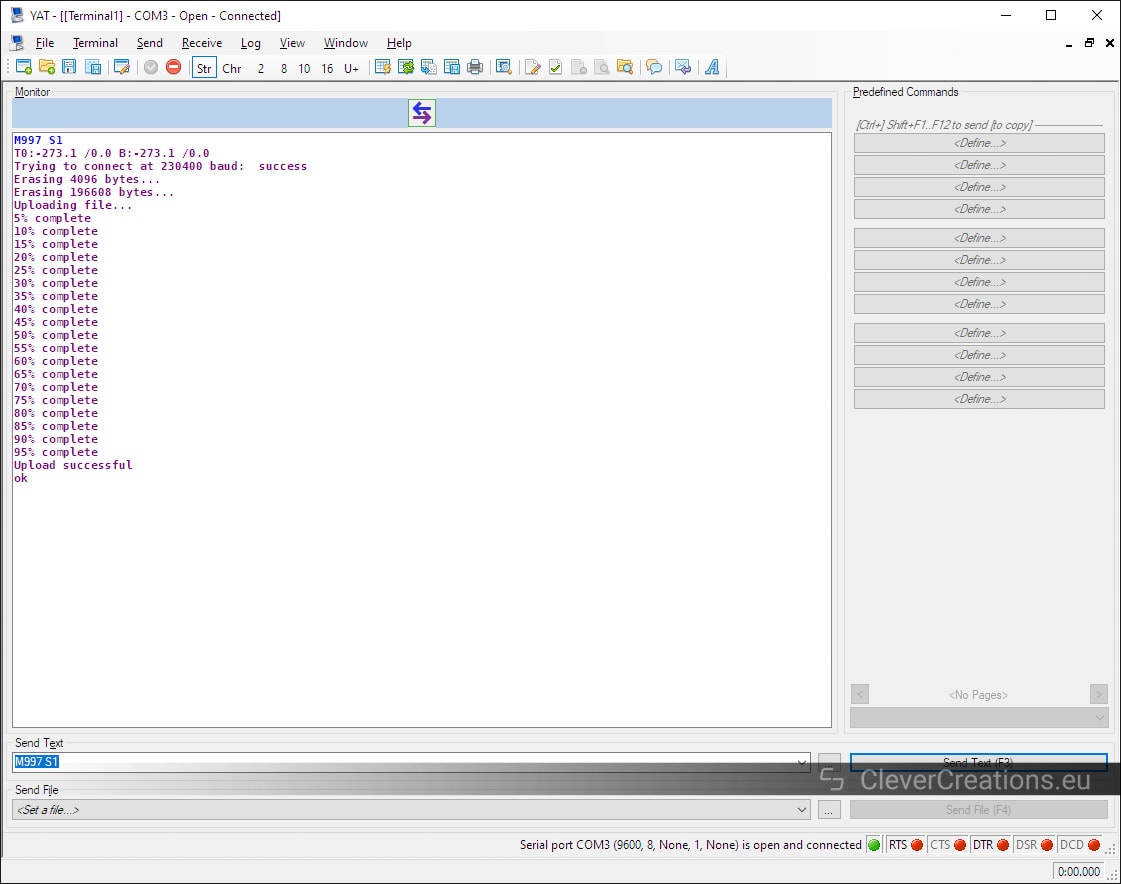
There are still a couple of things that need to be done after soldering the new module in place. The first is to update the firmware of the Wifi module. On the Duet this can be done as follows:
- Download the latest DuetWifiServer.bin from the Duet3D firmware page.
- Place the DuetWifiServer.bin in the /sys folder of the Duet SD card.
- Send an
M997 S1command to the Duet using the YAT terminal.
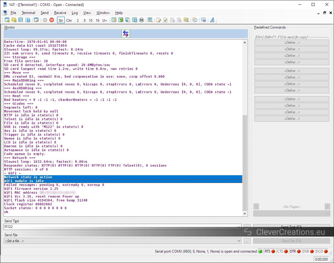
M552 S0 and following up with an M122 should now show a working Wifi module.After that, it is just a matter of connecting the Duet to your Wifi network as usual.
Conclusion
If you can’t connect to your Duet Wifi anymore, then there are a couple things you can try to fix the connection problems. If none of these work, it is possible that the ESP-12S or ESP-07S wireless module is broken.
No worries, there is no need to buy a brand new Duet 3D printer controller. With the right tools you can replace the module yourself and get your 3D printer or CNC up and running again.
It is important to not attempt this without access to a hot air rework station. With just a soldering iron it is practically impossible to keep all solder joints of the wireless module molten at the same time.
I would replace the onboard module with ESP8266 Esp-07 WIFI transceiver module, it has an external IPX antenna socket.
That would work well!
Could this guide be used to convert a Duet 2 Ethernet to Wi-Fi?
Good question! In theory, it should be possible. In practice, it might be difficult to desolder the Ethernet module because of its large size. We don’t have any hands-on experience with the Ethernet version, so we can’t tell for sure.
Yes, i just did it. Just unsolder the ethernet header pin then the rest is same step above
Thank you so much for this article! I have this 1.04 board when the WIFI LED went out and no WIFI is available anymore… So identical to your situation.
But before I order a new ESP-12S module I was wondering if it possible to install the
Espressif ESP-WROOM-02D/U instead?
Yes I had the same question. I am going from ethernet to wifi conversion, I just wanna ditch the cable so I’m going with ESP-07S for now. But I will add a separate BL module
for more options.
Thanks TIM!. This is an excellent step-by-step guide and very neat and complete. I am sure it will help many people to repair instead of replace their boards.
I suspected that I had a faulty WiFi module, but after updating the firmware to 3.5.3 (19 Sept 2024) the blue LED lit up and I can see it connected to my router. I however have a problem connecting to it using http://192.16.1.99 which is its IP address. I can also not ping it. Any advise would be highly appreciated. Duet 2 v.1.04a OBC with ESP-12S WiFi module.