
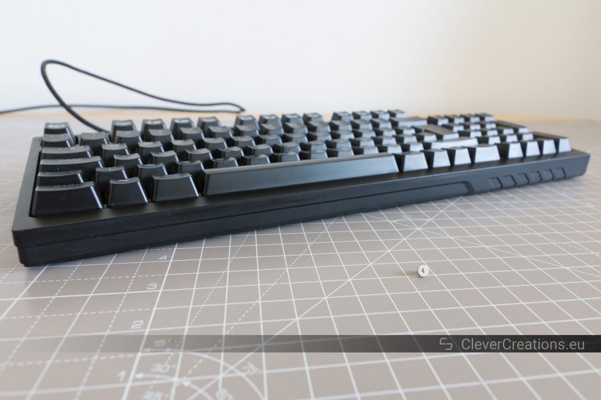
Keyboards with detachable cables can be very practical. The detachable cable allows the keyboard to be stored and transported more easily, and also makes the process of swapping out the keyboard painless.
The detachable cable is most often connected to the keyboard with a mini-USB or micro-USB connector. Unfortunately, while this system provides the benefits listed above, it also introduces a point of failure. The mini- or micro-USB port on the keyboard wears out and causes the keyboard to stop working properly. Common symptoms of this problem are the keyboard randomly disconnecting, or not being recognized by the PC at all.
In this article I will explain you how to repair a keyboard with a damaged USB port. I have also included a step by step guide on how to do this on a Cooler Master Quick Fire TK mechanical keyboard.
Before showing you how to fix keyboard problems caused by a damaged mini- or micro-USB port, I will first answer some frequently asked questions.
What Causes the USB Port on the Keyboard to Break?
The most common cause of the mini-USB or micro-USB port on a keyboard breaking is that it simply wears out. The port is rated for a limited number of connect-disconnect cycles, and eventually it stops carrying the signal from the connector properly.

Even if a connector or port is rated for a certain number of connect-disconnect cycles, the actual number of cycles before problems occur can be a lot lower. The majority of keyboards are mass-produced, and nowadays it is not uncommon for manufacturers to use cheaper, lower quality components in order to save costs. Lower quality components break a lot quicker than their quality counterparts.
Oftentimes this results in a product becoming unusable at some point, because of a couple of cents saved on something like a switch, USB port, etc.
</rant>
Luckily, it is not too hard to repair these problems.
How Can You Tell if the Problems are Caused by the Keyboard’s USB Port?
When a keyboard’s USB port starts failing, there are a couple of symptoms that can show up. For example, the keyboard will begin randomly disconnecting and reconnecting to the computer, or it will not be recognized by the computer at all. Sometimes, wiggling the cable connector in the port can solve the problem, but that is usually only temporary.
Before opening up and repairing the keyboard however, it is important to first exclude other possible causes of the problem. Try a different USB cable, different USB ports, and if possible connect the keyboard to a different device to see if it works there. Also make sure to install any required drivers for the keyboard.
If the keyboard has the same problem in all other configurations, then it is definitely the keyboard that is causing the issue.
If nothing else damaged the keyboard (e.g. liquid spilled over the keyboard), then it is likely that the USB port is what is causing the connection problems.
How Can You Repair the Mini- Or Micro-USB Port on a Keyboard?
There are two main ways in which the USB port on a keyboard can be fixed. The first one is to replace the USB port on the circuit board of the keyboard. The second one is to remove the USB port altogether and to solder the USB cable directly to the electronics of the keyboard.
Replacing the Mini- Or Micro-USB Port
The USB port on the keyboard can be replaced by desoldering the old port on the keyboard’s circuit board and soldering in a new one. This is quite tricky to do by hand with a soldering iron, however, because of the small pins on the port. If you want to try this, it is best to use a hot air rework station instead of a soldering iron.

At the time of repairing the Coolermaster Quick Fire keyboard I did not have access to a hot air rework station, so this method is beyond the scope of this article. If I get my hands on a second keyboard with this problem however, I will document the process with a hot air rework station and update this article.
The advantage of replacing the USB port is that the keyboard keeps its detachable cable, but there is a risk of the USB port developing the same issue in the future.
Soldering the USB Cable Directly to the Keyboard’s Electronics
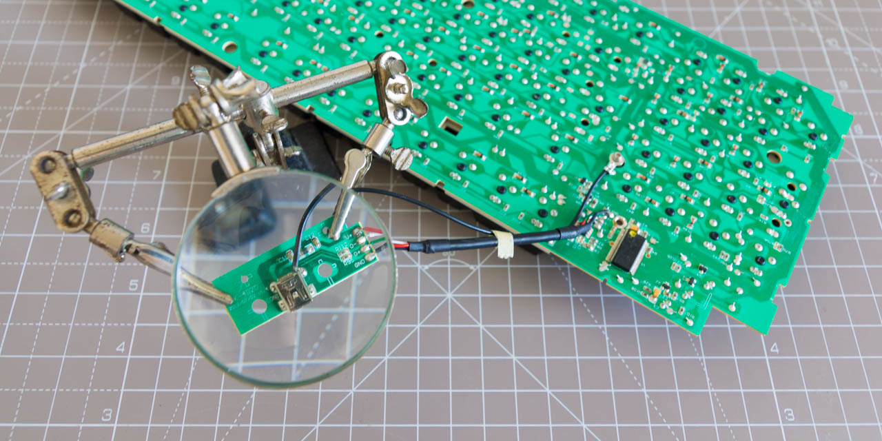
The alternative is to bypass the USB port altogether, and to solder the USB cable directly to the electronics of the keyboard. This can either be to a circuit board in the keyboard, or (as in the case of my keyboard) to an internal USB cable. This fix is a lot easier, as it only involves manually soldering four wires.
When repairing the keyboard like this, it does lose the detachable cable functionality. But you will never have to worry about problems with the mini-/micro-USB port again.
I personally rarely detached the cable anyway (and yet the USB port still broke), so not being able to detach it is not an issue for me. It’s still not ideal, but it beats buying a new keyboard.
Further down the page I have added a step-by-step guide on how to solder the USB cable directly to the keyboard’s electronics.
Does This Guide Also Work for Keyboards Other Than the CM Quickfire?
While the guide below shows the repair process on the CoolerMaster QuickFire TK keyboard, it should be possible to use it for other keyboards as well. The steps will be fairly similar on other keyboards.
What is important is to identify where you should solder the wires from the USB cable to.
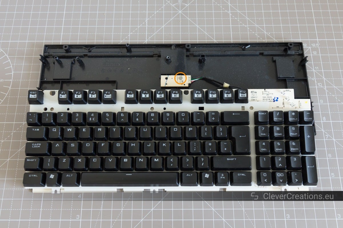
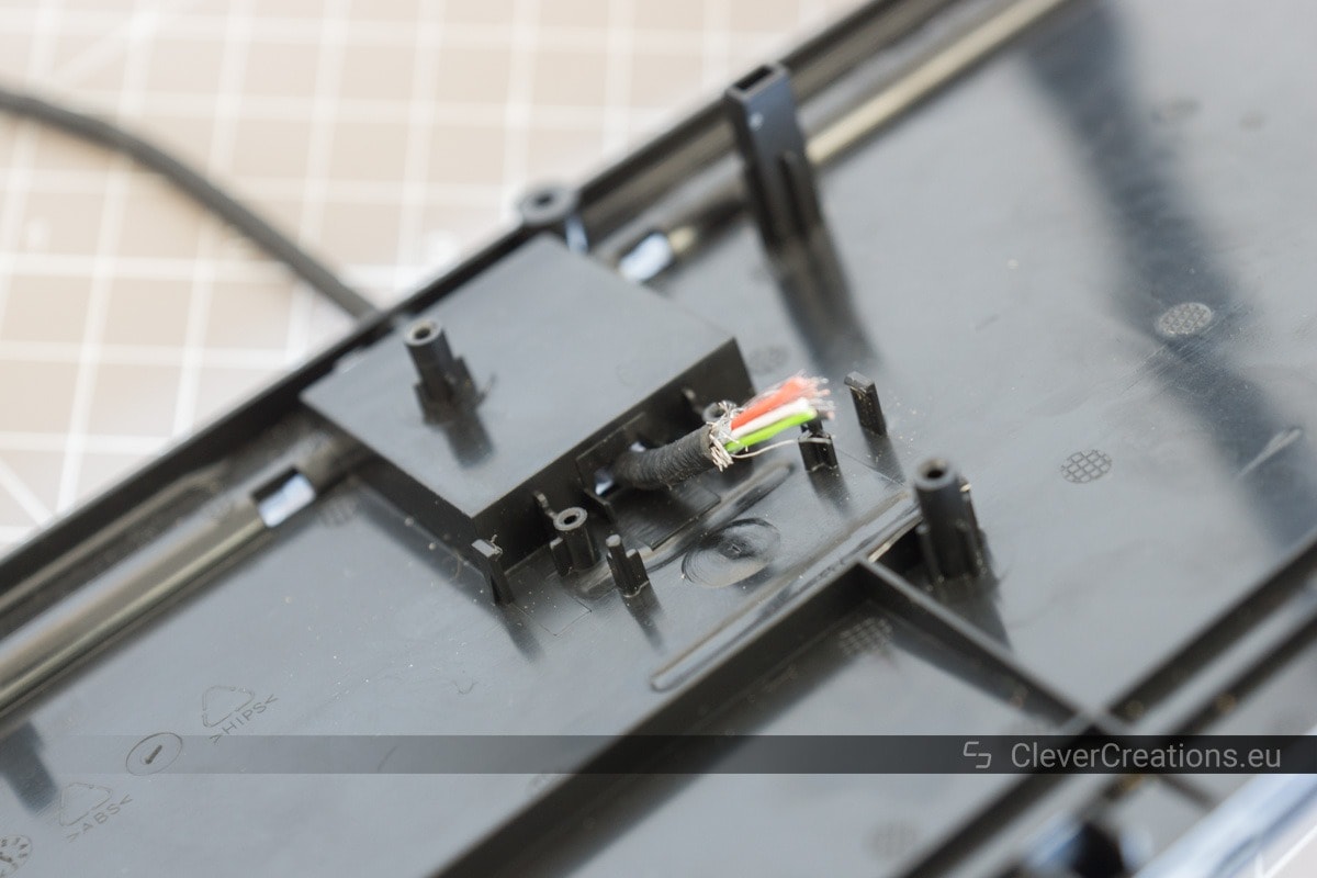
In the case of the CoolerMaster QuickFire, the keyboard has an internal cable that carries the USB signal. I could simply attach the external USB cable to the internal one.
I suspect many other CoolerMaster keyboards to have a similar configuration.
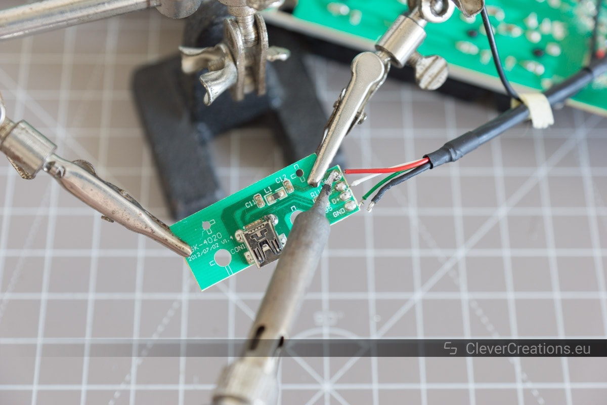
Other keyboards that are not wired like this might still have pads for the USB signal on the circuit board. These are usually labelled something like VCC, D-, D+ and GND and can be found close to the USB port.
How to Repair a CoolerMaster Quick Fire TK Keyboard
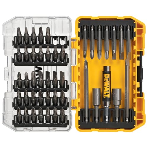
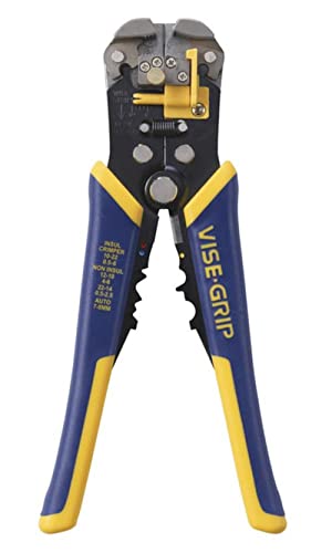
What You’ll Need


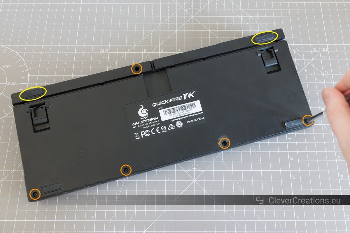
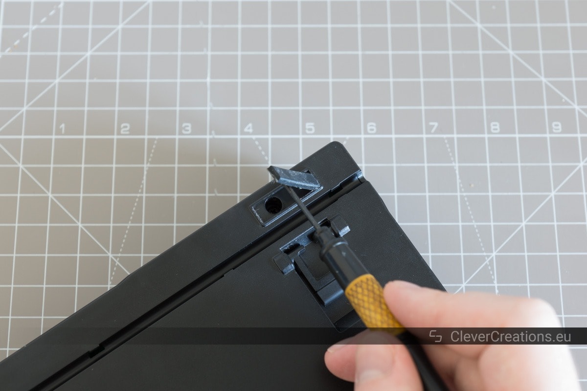
Opening the Keyboard
Removing the PCBs

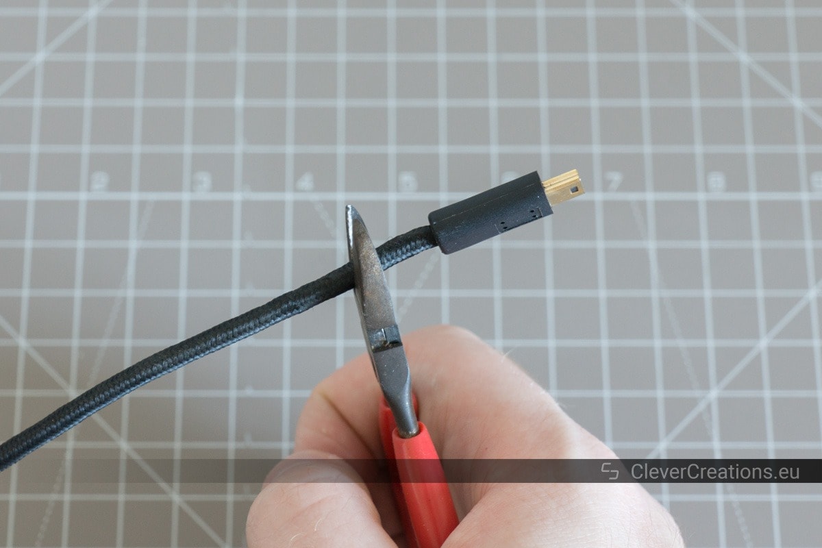
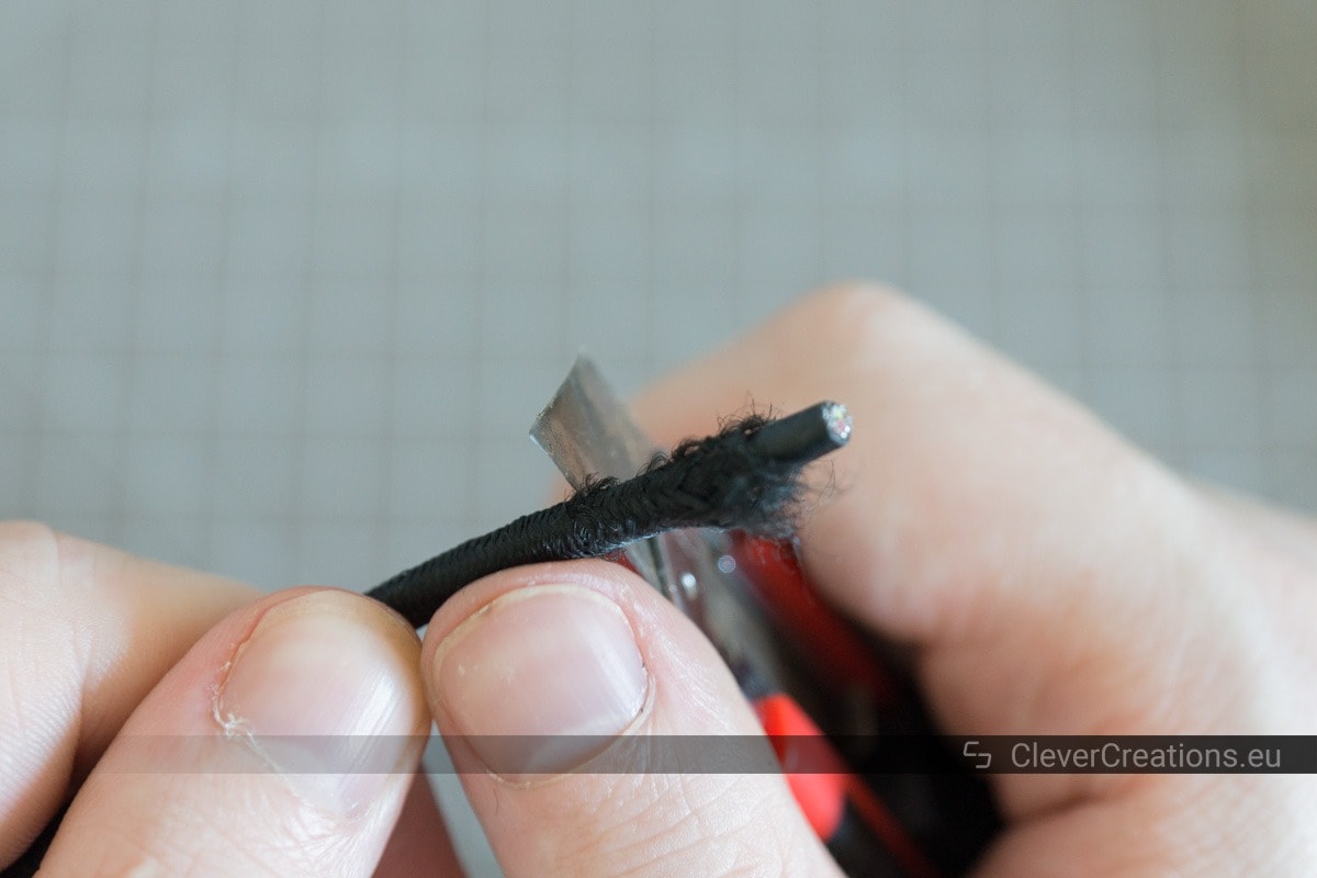
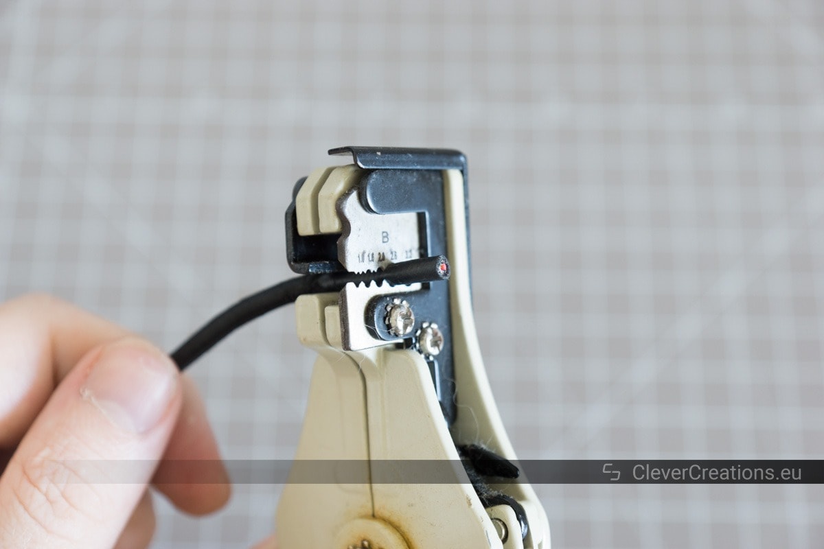
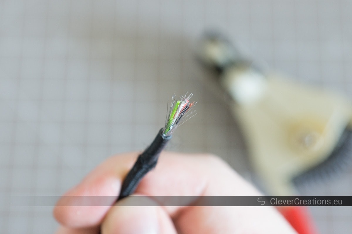
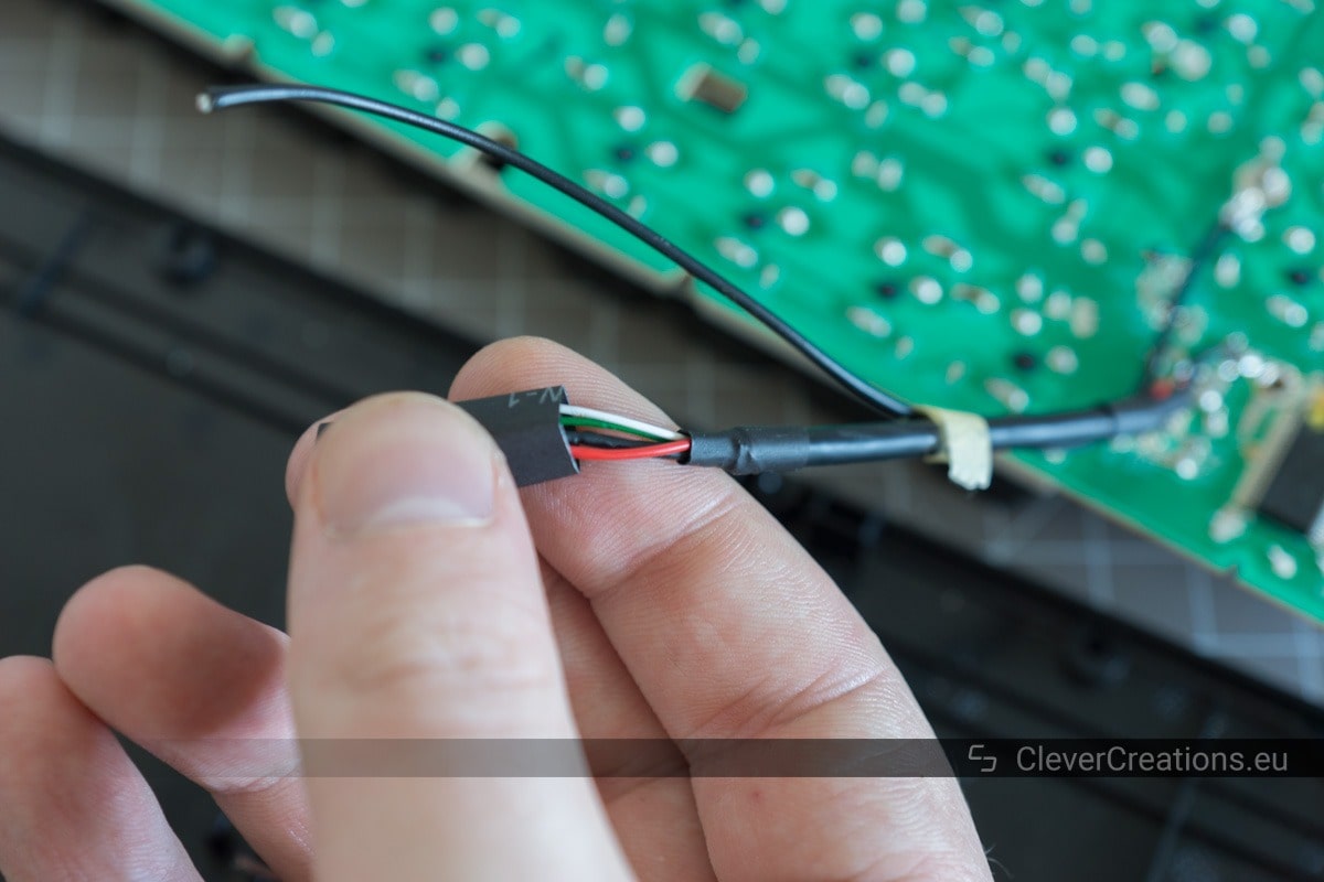
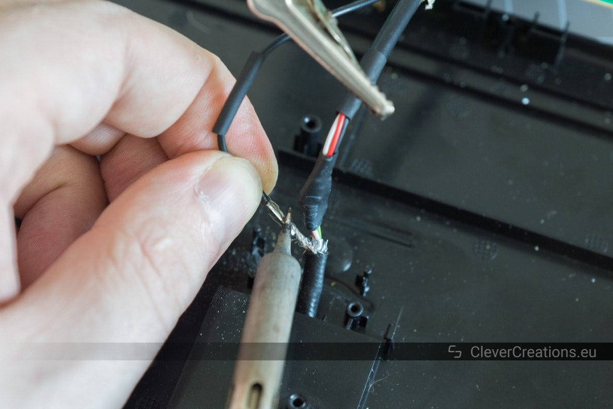
Modifying the Detachable USB Cable

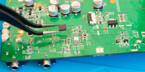
Removing the Small PCB

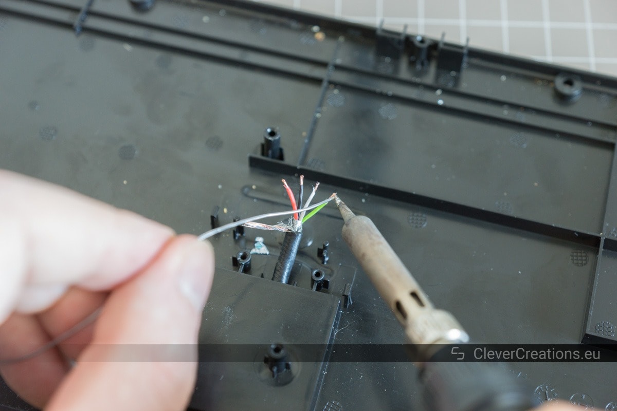
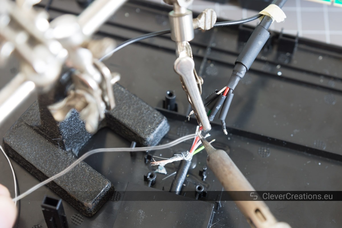
Soldering the USB Wiring


Finishing Up
A Summary of the Repair Process
- Unscrew the screws from the bottom of the keyboard.
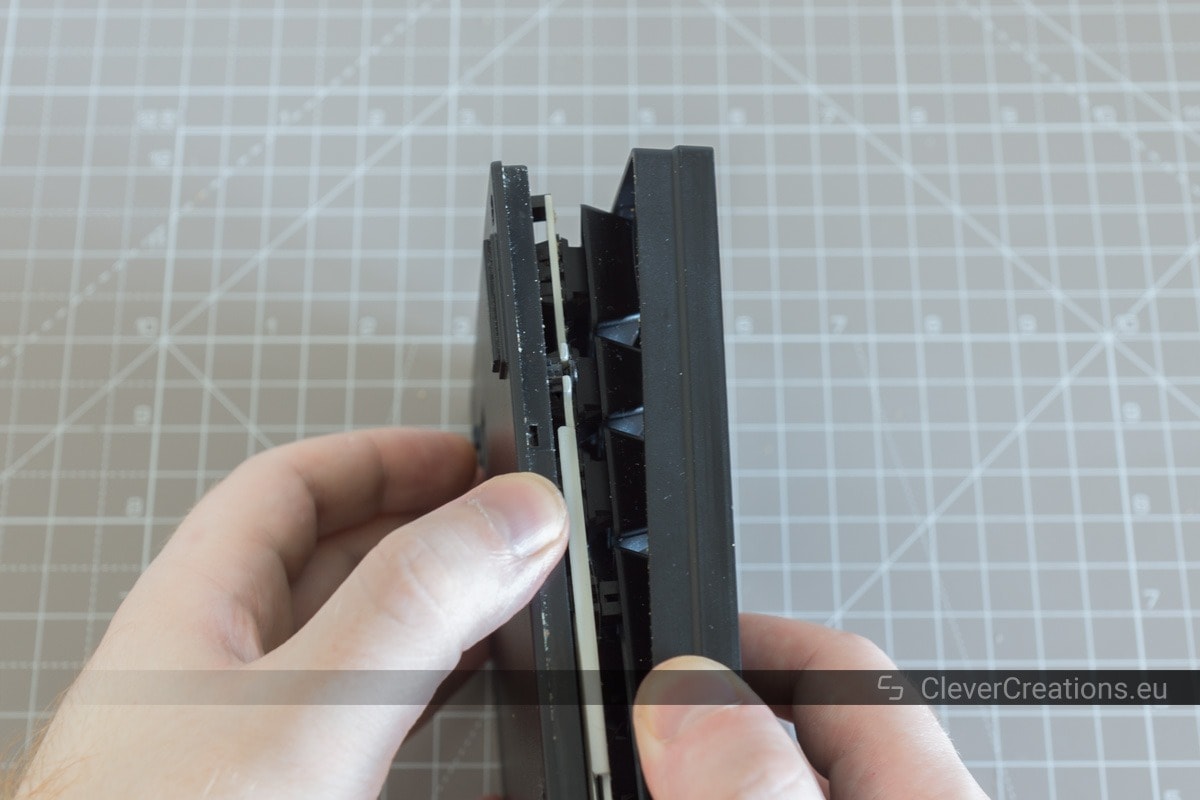
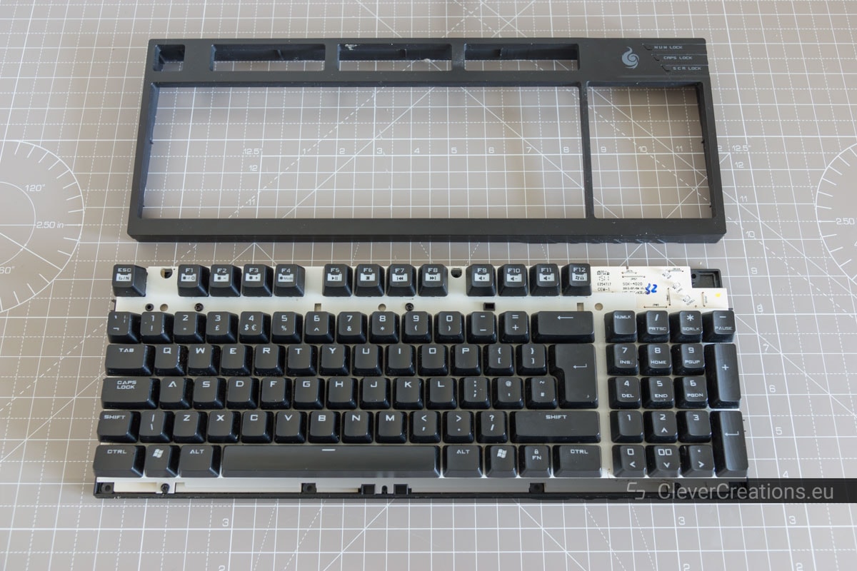
- Remove the top plastic cover.
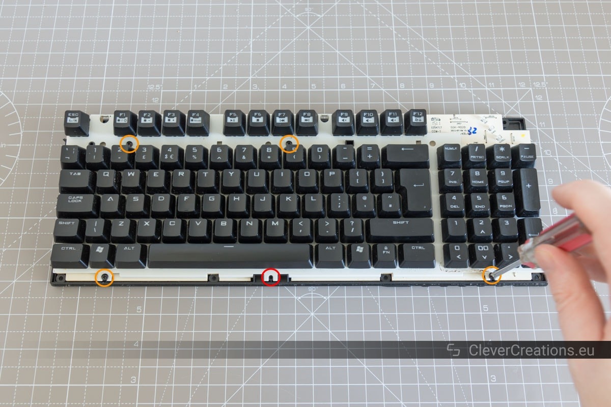
- Unscrew the screws that hold the main PCB in place.
- Move the main PCB out of the way and detach the smaller PCB.
- Modify the detachable USB cable to get it ready for soldering.
- Desolder the USB wiring from the small PCB.
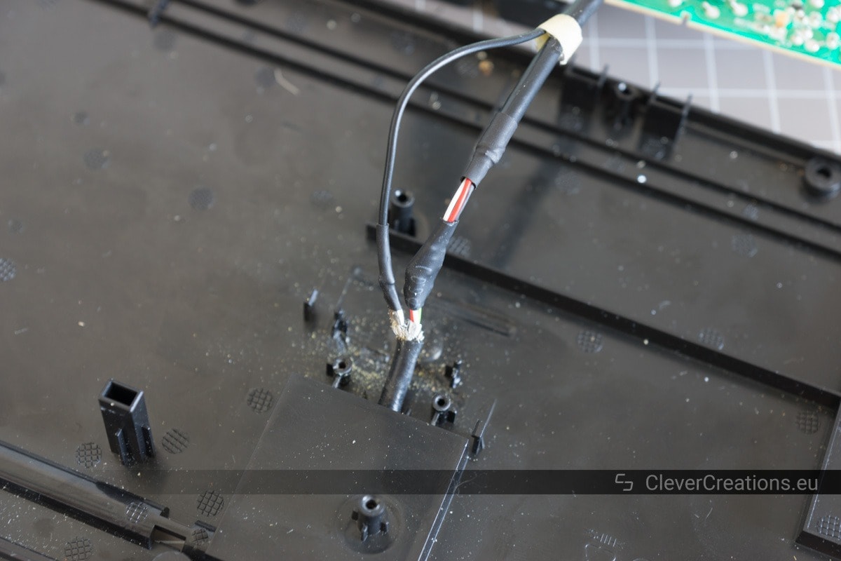
- Solder the two sets of USB wiring together.
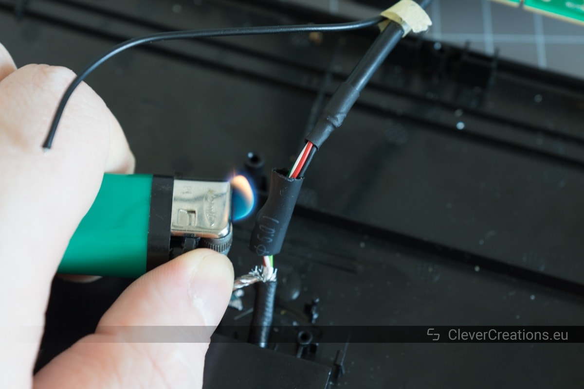
- Heat shrink the solder joints.
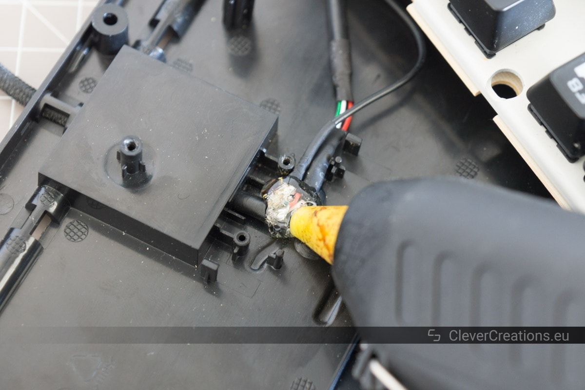
- Hot glue the USB cable in place.
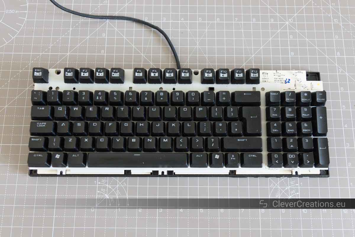
- Test the keyboard.
- Reassemble the keyboard.


Conclusion
Ever since soldering the USB cable directly to the keyboard, it has been working perfectly. No more random disconnects or other problems.

Thankyou so much for making this article. I thought I was going to need to replace the board or even through the keyboard away. I tried your fix and bam, everything is up and running again.
Hi Travis. You are welcome! Thank you for sharing your results.
This is just what I need it! Have the same keyboard and one of the 5 pins on the usb bent. The small pcb have some resistors or capacitors, not sure what. Are they not needed?
I’ve always wanted to have a kit for soldering small things and fixing these simple things.
I was wondering if you have repaired any duckey keyboards charging port on key board to usb cable.would appreciate help on this topic as I can not find where to buy the part I need
Hi Rick,
I can’t say that I have, but it shouldn’t be too hard to figure out what part it is and find a store that sells it. Do you have a picture of the charging port? Preferably one that also shows the circuit board that it is attached to.
Tim