

Nowadays, you can find 3D printers in all shapes and sizes. The most common one that you can see is probably the Cartesian style 3D printers like the Ender 3 and the Prusa i3 MK3S+. But one more recent and arguably superior style is the CoreXY 3D printer arrangement.
CoreXY 3D printers are increasing in popularity amongst hobbyists and professionals due to their rigid cube-shaped design and high printing speeds. The coreXY setup has less moving parts than a Cartesian printer, and offers better print quality.
A popular 3D printer in this style is the Voron 2.4. It has a solid structure, is widely configurable, and delivers excellent print quality at high speeds, all while remaining relatively affordable. For these main reasons, it came out on top of this list of the best CoreXY 3D printers.
In this article, we will go over the full list and explain what you need to look out for when buying a CoreXY machine. So without further ado, let’s get started and figure out which is the best CoreXY printer for your needs.
| CoreXY 3D Printer | Summary | Build Volume(s) | Price (~) | Best Offer |
|---|---|---|---|---|
| Voron 2.4 | Best overall | 250 x 250 x 250 mm 300 x 300 x 300 mm 350 x 350 x 350 mm | $879-$1059 | |
| TRONXY X5SA | Best on a budget | 330 x 330 x 400 mm | $359 | |
| Vivedino Troodon | Best high-end | 300 x 300 x 400 mm 400 x 400 x 500 mm | $1674-$2144 | |
| Rat Rig V-Core 3 | Most configurable CoreXY kit | 300 x 300 x 300 mm 400 x 400 x 400 mm 500 x 500 x 500 mm | $560-$2000 | |
| Creality Ender 6 | Best Creality CoreXY | 250 x 250 x 400 mm | $550 | |
| Voron 0.1 | Smallest CoreXY | 120 x 120 x 120 mm | $453 | |
| Creality CR-30 | Best infinite Z-axis | 200 x 170 x ∞ mm | $1099 | |
| Creativity 3D Elf | Best dual Z-axis | 300 x 300 x 350 mm | $399 | |
| E3D ToolChanger | Most versatile | 200 x 300 x 300 mm | $2200 |
What is a CoreXY 3D Printer?
The CoreXY style started as an MIT project by Ilan Moyer in 2011. The project’s original aim was to negate the side-effects of traditional cartesian motion systems by eliminating the serially stacked axes (one motor pushing the mass of another).
In a CoreXY printer, two stepper motors are stationary. It uses a clever belt system to move the print head in both the X and Y directions. The stationary motors result in less moving mass, which in turn means that higher print speeds and accelerations can be achieved without sacrificing too much print quality.
Core XY Advantages and Disadvantages
In a Cartesian style 3D printer, each stepper motor moves independently of the other. While it leads to a more straightforward design, the disadvantage is that the Y-axes motor has to move the heavy print bed back and forth. The Z-axis, too, has to lift the mass of the X-axis beam, the hot end, and the X-axis stepper motor, limiting the printing speeds and printer size.
In a CoreXY system, the XY stepper motors work in tandem to move the hotend. There are no moving stepper motors, and the load of the hot end beams is divided equally amongst the two stepper motors. It leads to a lighter hot end design, faster printing speeds, higher print accuracy, a solid printer frame, and a compact form factor.
The disadvantages, however, are that a CoreXY 3D printer uses a complicated belt and pulley arrangement. You need to make sure that the belts are aligned perfectly and are parallel to each other. The longer belt length also mandates that the belts are properly tensioned and aligned. If not, it will lead to dimensional inaccuracies in your 3D prints.
All of this means that while CoreXY 3D printers can be superior to Cartesian variants, they do require a bit more tinkering and setup time to get them running perfectly. Going with a reliable and qualitative option is therefore the best thing you can do to save yourself time and effort.
Now, let’s look at which CoreXY 3D printers deserve your money.
The Best CoreXY 3D Printers in 2024
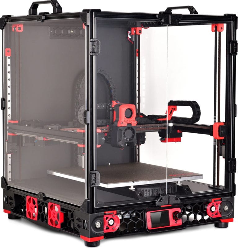
The Voron 2.4 is a DIY CoreXY 3D printer that came to be due to the Voron project initiated in 2015. The Voron 2.4 is one of the five 3D printers under the Voron initiative and is the most popular and versatile at the moment.
Like all Voron 3D printers, the Voron 2.4 comes as a kit, and you can choose from three different build volumes for your build. The kit comes with a PEI magnetic build plate for easy print removal, Moons’ stepper motors for high reliability, all-metal titanium alloy print head with a direct drive extruder to let you print with a wide variety of materials.
A unique aspect of the 2.4 is its all-belt system, even on the Z-axis, which makes for a more straightforward bed leveling process. The motion of these axes themselves is stabilized with the help of stainless steel linear rails for smooth and precise movement.
The Voron 2.4 3D printer kit gives you ample opportunities to build your 3D printer the way you like it. It is well-documented, has a strong and active community, is fully open source, and provides impressive features considering the price point, making it one of the overall best CoreXY 3D printers. If you like DIY stuff (i.e. building your own 3D printer) and want a robust printer with great print quality, it is the perfect fit for you.
Standout Features
- All metal titanium alloy hotend
- Scalable build volume
- Open-source design
Technical Details |
|
|---|---|
| Build volumes | 250 x 250 x 250 mm 300 x 300 x 300 mm 350 x 350 x 350 mm |
| Feeder system | Direct Drive or Bowden |
| Frame | Aluminum, 3D printed parts |
| Max. hot end temperature | 300°C |
| Bed leveling | Automatic |
| Materials | ABS, PLA, TPU, nylon, carbon fiber, PVC, HIPS |
What We Like
- Wide material compatibility
- Excellent community support
- Automatic bed leveling
Could Be Better
- Requires assembly
- Complicated Z-axis system
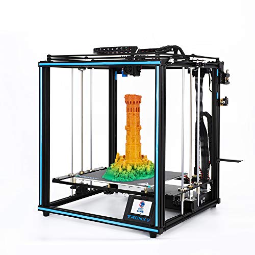
Like the Voron 2.4, the Tronxy X5SA comes as a 3D printer kit. It boasts an impressive build volume of 330 x 330 x 400 mm for just under $350.00 and is an excellent value for money option in this price range.
The Tronxy X5SA comes with a Bowden style extruder setup for printing at faster speeds and fully benefiting the CoreXY design. It offers filament run-out detection, a resume print function, an auto-bed leveling system, includes a coated glass bed, and has a 3.5-inch touchscreen for user convenience during the 3D printing process.
Overall, the Tronxy X5SA is one of the best CoreXY 3D printers if you want a significant build volume on a budget and want to get your hands dirty building your own machine. It offers excellent features and decent print quality and will fit hobbyist 3D printers as well as a school environment.
Standout Features
- Filament run-out detection
- Touchscreen
- Auto-bed leveling
Technical Details |
|
|---|---|
| Build volume | 330 x 330 x 400 mm |
| Feeder system | Bowden |
| Frame | Aluminum, sheet metal |
| Max. hot end temperature | 275°C |
| Bed leveling: | Auto |
| Materials | ABS, PLA, TPU, nylon, carbon fiber, PVC, HIPS |
What We Like
- Cheap and affordable
- Decent build quality
- Fast printing
Could Be Better
- Plastic extruder
- Assembly is tricky for beginners
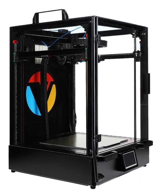
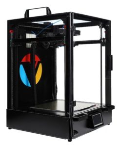
The Vivedino Troodon is a premium CoreXY 3D printer that comes with the highest specifications and offers top-of-the-line features for the best 3D printing experience. Unlike the previous two CoreXY printers, the Troodon comes fully assembled. In terms of configurability, you can choose from two different build volumes.
The spec sheet is relatively similar to the Voron 2.4. Just like it, the Troodon comes with a direct drive extruder, a magnetic PEI flexible build plate, and an all belt-driven motion system with precision linear rails. Additionally, you get a 32-bit motherboard with a TMC2660 stepper driver, an automatic bed leveling probe, and a built-in HEPA filter to filter out 3D printer fumes.
The Vivedino Troodon is fully packed with features and offers everything you would expect from a premium 3D printer. At its price point, it is not for beginners and amateurs in 3D printing; however, considering it comes fully assembled, it will make an excellent choice for prosumers and professionals looking for a 3D printer that rapidly delivers high-quality prints.
Standout Features
- HEPA air filter
- 32 Bit controller with TMC2660 stepper drivers
- Wireless control via Wi-Fi module
Technical Details |
|
|---|---|
| Build volumes | 300 x 300 x 400 mm 400 x 400 x 500 mm |
| Feeder system | Direct Drive |
| Frame | Aluminum, sheet metal |
| Max. hot end temperature | 270°C |
| Bed leveling | Auto |
| Materials | PLA, ABS, PVA, HIPS, PETG, Nylon, Wood, PC, Carbon Fiber, etc. |
What We Like
- Uses premium components
- Excellent build and print quality
- Auto-bed leveling
Could Be Better
- 'Clone' Duet 2 Wifi Electronics
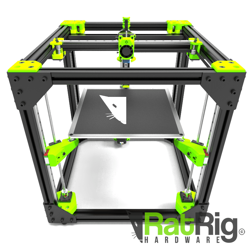
The RatRig V-Core 3 is a premium DIY 3D printer kit aimed at advanced-level users who want to customize their 3D printing experience fully. Due to higher-end components, it boasts top-of-the-line features and high printing quality.
This CoreXY 3D printer is available in three different build volumes, with the most extensive configuration giving you a whopping 500 x 500 x 500 mm of print volume. You get belt-driven X and Y axes and a unique 3-point kinematic bed leveling system on the Z-axis for a perfectly leveled print bed each time. MGN 12 precision linear rails fully support the motion system for smooth motion.
The RatRig V-Core 3 offers excellent value and gives you complete control over the design of your 3D printer by allowing you to choose the exact components and upgrades you need. There is good documentation available with many build videos. Similarly, its users provide good community support.
Altogether, the RatRig V-Core 3 is a great fit for professionals and seasoned 3D printer users who want to build a high-end machine with excellent features and do not mind paying a premium for it.
Standout Features
- Fully customizable kit
- 3 Point kinematic bed
- Quality MGN12 linear rails
Technical Details |
|
|---|---|
| Build volumes | 300 x 300 x 300 mm 400 x 400 x 400 mm 500 x 500 x 500 mm |
| Feeder system | Direct Drive or Bowden |
| Frame | Aluminum and 3D printed parts |
| Max. hot end temperature | 450°C (Mosquito Hotend) |
| Bed leveling | Auto or Manual |
| Materials | PLA, ABS, PVA, HIPS, PETG, Nylon, Wood, PC, Carbon Fiber, etc |
What We Like
- Can print advanced materials
- Easy to scale and configure
- High accuracy
Could Be Better
- Requires technical expertise
- Time-intensive build

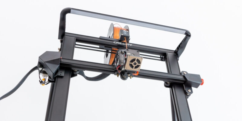
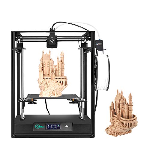
The Creality Ender series 3D printers deliver good-quality prints while providing excellent value for money and accessible to many users. The Creality Ender 6 is Creality’s attempt at a CoreXY 3D printer, and it combines the features of the Ender 3D printer’s design along with the benefits of the CoreXY design.
The Ender 6 is a fully enclosed 3D printer with a decent build volume of 250 x 250 x 400 mm. It comes with filament run-out detection, a resume printing function, and a touch screen with an updated UI for ease of use. The downside is the manual bed leveling, which is cumbersome considering the bed size and can lead to print failures. It is possible to upgrade it with a BLTouch leveling sensor, however, taking away the need for manual leveling.
Overall, the Creality Ender 6 is a great overall package with all the basic features you need and gives a decent print quality. It is amongst the best CoreXY 3D printers for beginners and can be safely used in classrooms and home setups due to its fully-enclosed design.
Standout Features
- Ultra silent motherboard
- 4.3" HD Touch Screen
- Fully-enclosed design
Technical Details |
|
|---|---|
| Build volume | 250 x 250 x 400 mm |
| Feeder system | Bowden |
| Frame | Aluminum and plastic |
| Max. hot end temperature | 240°C |
| Bed leveling | Manual |
| Materials | PLA/TPU/ABS/PETG |
What We Like
- Easy to use
- Affordable
- Fully enclosed design
Could Be Better
- Manual bed leveling
- Print quality does not stand out
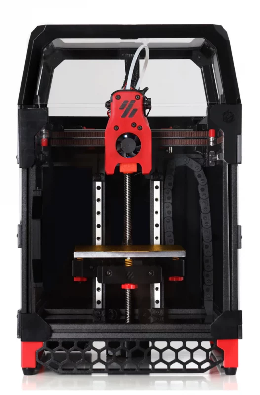
The best CoreXY 3D printers usually come with significant build volumes to take advantage of the high-printing speeds provided by the CoreXY style setup. However, the Voron 0.1 is an exception and caters to users who want the benefits of some of the best CoreXY 3D printers, albeit in a small and compact form factor.
The build volume is a meager 120 x 120 x 120 mm, which is only fit for printing smaller models. Nonetheless, you get an all-metal titanium print head for maximum material compatibility and an adjustable magnetic PEI print bed for easy print removal. The X and Y axes are belt-driven, while the vertical Z-axis has a lead screw for the print bed’s movement.
The Voron 0.1 is a feature-packed small 3D printer with high-end features meant for both prosumers and professionals in the industry. It can also be a great beginner’s 3D printer for trying out exotic print materials. And if you can get away with the small build volume, the Voron 0.1 is as good as any other premium FDM printers out there.
Standout Features
- Compact build
- High-quality enclosed panels
- Control via Raspberry Pi
Technical Details |
|
|---|---|
| Build volume | 120 x 120 x 120 mm |
| Feeder system | Direct Drive |
| Frame | Aluminum and 3D printed parts |
| Max. hot end temperature | 300°C |
| Bed leveling | Manual |
| Materials | ABS, PLA, TPU, nylon, carbon fiber, PVC, HIPS |
What We Like
- Small footprint
- Wide material compatibility
- Genuine high-end components
Could Be Better
- High cost for its volume
- Only comes in kit form

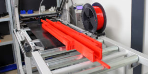
The Creality CR-30 is a unique 3D printer with a very different design. Instead of a traditional print bed on the Z-axis, it uses a conveyor belt. It builds on the concept of Karl Brown and Bill Steele’s 3DPrintMill 3D printer.
The CR-30’s continuously moving conveyor belt lets you print infinitely long objects on the Z-axis. Its Nylon print surface is excellent for bed adhesion, and the prints easily fall off the edge of the conveyor belt once their printing is complete.
This CoreXY printer’s XY plane is inclined at a 45° angle to the printing surface, which gives it a unique printing angle and offsets any drawbacks caused due to the typical vertical nozzle arrangement. You also get a dual-gear metal extruder and a filament detection system as additional features for extra reliability.
While the CR-30’s design stands out amongst this list of best CoreXY 3D printers, it is not the ideal 3D printer for a beginner. Nonetheless, if you print extremely large objects and need a printer specifically for these use cases, it is an excellent match for your 3D printing needs.
Standout Features
- Infinite Z-axis design
- Silent 3D printing
- Multiple printing modes
Technical Details |
|
|---|---|
| Build volume | 200 x 170 x ∞ mm |
| Feeder system | Bowden Drive |
| Frame | Aluminum |
| Max. hot end temperature | 240°C |
| Bed leveling | Factory leveled |
| Materials | PLA/TPU/ABS/PETG |
What We Like
- Prints infinitely long models
- Automatic print removal
- No need for bed leveling
Could Be Better
- Large footprint
- Requires lots of fine-tuning
The Creativity 3D Elf is a budget CoreXY 3D printer with a great mix of features and innovation at an affordable price. For example, it comes with a dual Z-axis linear rod design for a stable and precise 3D printing experience.
The printer itself comes as a partially assembled kit, and you can start 3D printing with it in less than an hour This makes it an excellent beginner-friendly option. You get a heated bed, a proprietary nozzle that reaches up to 260 °C, and a 32-bit motherboard with silent TMC 2208 stepper drivers. It also has a 3.5-inch touchscreen for easy use and accessibility.
Considering the price point and the features, the Creativity 3D Elf is a great beginner 3D printer that delivers decent print quality. You get all the things you’d need to print basic materials and can be further upgraded with advanced features to meet more high-end needs.
Standout Features
- Dual Z-axis design
- Easy to assemble
- High-temperature hot end
Technical Details |
|
|---|---|
| Build volume | 300 x 300 x 350 mm |
| Feeder system | Direct Drive or Bowden |
| Frame | Aluminum and Metal |
| Max. hot end temperature | 260°C |
| Bed leveling | Manual |
| Materials | PLA, ABS, HIPS, Flexible, Soft Rubber, Carbon Fiber, TPU, etc. |
What We Like
- Stable and accurate printing
- Neat cable management
- Beginner-friendly design
Could Be Better
- Open-frame design
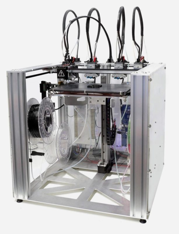
The E3D ToolChanger motion system is one of the most unique and innovative 3D printer designs to date. It lets you use additive and subtractive manufacturing along with laser inspection, all in a single machine. You get to do all of this due to its unique tool-head changing system.
The E3D tool changer supports up to 4 tool heads at a time, which you can configure with various modules. You can choose between different 3D printer hot ends, inspection tools, and a subtractive mill tool with it. Using multiple Hemera extruders, for example, enables you to execute actual multi-material 3D printing without any purge tower and saves a lot of printing filament compared to swapping out filaments in a single extruder.
In terms of features, you get a Duet 2 Wi-Fi motherboard, which has plenty of connectivity ports and delivers one of the best 3D printing experiences. In terms of build quality, you get genuine Hiwin linear rails, Gates belts, and a solid metal structure, all of which come pre-assembled out of the box.
Considering its price point and the use of high-end components, it is not for the average 3D printer user. However, if you want a machine that lets you manufacture, finish and inspect all in a single system, the E3D ToolChanger is the most versatile CoreXY solution around.
Standout Features
- Unique quadruple toolhead design
- Duet Wi-Fi controller
- High-temperature heated bed
Technical Details |
|
|---|---|
| Build volume | 200 x 300 x 300 mm |
| Feeder system | Direct Drive or Bowden |
| Frame | Aluminum, 3D printed parts |
| Max. hot end temperature | 500°C |
| Bed leveling | Manual |
| Materials | PLA, ABS, PVA, HIPS, PETG, Nylon, Wood, PC, Carbon Fiber, etc. |
What We Like
- True multi-material printing
- Can inspect and machine 3D prints
- Robust build quality
Could Be Better
- Complex electronics and operation
- High price
What to Pay Attention to When Buying a Corexy 3D Printer
Build Volume
Due to their design, the best CoreXY 3D printers can utilize their build volume very efficiently. Typically, these printers have larger build volumes than their Cartesian counterparts to take full advantage of the faster printing speeds. In fact, there is often not much difference between the footprint of a CoreXY 3D printer and its build volume.
The build volume of your ideal CoreXY 3D printer dramatically depends on its application. If you’re going to print larger-sized objects, and your main goal is to print faster, 3D printers like the Voron 2.4 and the RatRig V-Core 3 provide considerable print volumes. Whereas, if you need a small and compact 3D printer for accurate yet fast 3D prints, the Voron 0.1 is an excellent option in the range.
Usually, though, a build volume of 300 x 300 x 300 mm covers a wide range of prints and gives you a nice balance between build volume and price.
Print Speed
Many of the best CoreXY 3D printers can quickly achieve printing speeds of up to 150 mm/s, which is already fast, and if you are willing to tune them further, you can promptly get print speeds beyond 250 mm/s, at least. In comparison, a Cartesian 3D printer can print only at about 90-100 mm/s without compromising print quality.
With faster printing speeds you get a quicker turnaround time, save on 3D printing electricity costs due to the lesser duration of prints, and you can re-iterate your designs quicker, leading to a faster production cycle. And the best CoreXY 3D printers let you do all of that without losing print accuracy or print quality.
Print Resolution
Print resolution directly translates to the print quality of any 3D printer, and it is often used in sync with the nozzle size and the layer height. Printing at a high layer height with larger nozzles, leads to reduced print resolution and print quality. On the other hand, a smaller nozzle size will let you print at small layer heights, increasing the print’s resolution and quality.
By default, almost all of the CoreXY printers in the list come with a 0.4 mm nozzle size, and it lets you comfortably print at layer heights of 0.12 – 0.28 mm. Usually, though, a small-sized CoreXY 3D printer will give you better-looking and high-resolution prints than a sizable 3D printer due to its small, sturdy, and rigid frame. The smallest of them, the Voron 0.1, can print at a layer of 0.05 mm, giving you the highest print resolution amongst the lot.
If you prioritize print quality and can get away with a decent build volume, Voron 2.4 and the Creality Ender 6 are the best CoreXY 3D printers that let you easily upgrade the entire hot end, nozzle setup to suit your needs.
Number of Extruders
If you’re planning on executing multi-material 3D prints, a dual extruder 3D printer will help you out immensely. You can choose to do multi-color 3D printing or use water-soluble PVA supports on the secondary extruder to print intricate and complex 3D models.
In the list, only the E3D Tool Changer motion system comes with a multi-extruder setup. You can hook up to four tool heads/extruders and execute actual multi-material 3D printing with it, and it uses separate interchangeable tool heads. You won’t have to waste filament with any purge towers nor lose any building area due to a secondary extruder on the print carriage.
However, the downsides of such a system are its high price, need for technical expertise, and regular maintenance owing to the system’s complexity. So, you should get a 3D printer with multiple extruders only if you want to carry out multi-material 3D printing regularly.
Filament Compatibility
The significant advantage of a CoreXY design is that you can easily enclose the 3D printer with panels on all sides. It aids in printing temperature-sensitive materials like ABS, Nylon, and even PETG. While an enclosed design is one factor in material compatibility, having an all-metal hot end and a heated bed is another.
Every CoreXY 3D printer in the list comes with a heated bed and a hot end that can reach up to 260 °C. It lets you quickly print with most common materials like PLA, ABS, PETG, and Nylon. These materials are enough to cover most of your 3D printing needs, even in a professional setting.
Then you have 3D printers like the Voron 2.4, Voron 0.1, E3D ToolChanger, and the RatRig V Core-3, which let you use high-temperature hot ends like the Phaetus Dragon hot end, which is rated to go up to 500 °C. This lets you work with the most advanced 3D printing materials, like PEEK, PEI, PolyPropylene, and PolyCarbonate.
Having a direct drive extruder, as opposed to a Bowden extruder that separates the stepper/drive gear arrangement and hot end, allows you to reliably 3D print with flexible filaments such as TPU.
Kit vs Pre-assembled
When you want to purchase a CoreXY 3D printer, you have two options – get it as a kit or buy one that’s preassembled. The latter one will be a plug-n-play type of solution, while the kit will require you to spend a considerable amount of time fine-tuning the 3D printer’s assembly.
If you choose to go with a CoreXY 3D printer kit, you will have the option to customize certain aspects of your machine while decreasing 3D printer cost compared to a fully assembled printer. The kit will give you detailed knowledge of the inner workings of the 3D printer, which will, later on, help you diagnose and fix issues.
However, you need to have the technical expertise to assemble the kit correctly; otherwise, an improper assembly might give you poor results. A pre-assembled 3D printer is a ready-to-use machine that’s pre-configured and calibrated right out of the factory, and even a novice 3D printer user can get started with it.
Is CoreXY Is Corexy Better Than Cartesian??
Some of the best coreXY 3D printers are definitely better than a Cartesian 3D printer in terms of print speeds, material compatibility, enclosed design, and efficient utilization of print space.
Do CoreXY 3D Printers Provide Good Quality Prints?
Not necessarily. The quality of the prints largely depends on the fine-tuning of the 3D printer’s various components and slicer settings. However, CoreXY 3D printers can deliver good quality prints at faster printing speeds of 150+ mm/s.
Is Assembling a CoreXY 3D Printer Difficult?
The assembly of a CoreXY 3D printer can be complicated for a novice or a beginner in 3D printing. It takes time to assemble the frame structure neatly and adequately tension the belts to get the best results. Still, partially assembled kits are available, like the Creality Ender 6, making it easy for beginners.
What is a CoreXZ Printer?
A CoreXZ printer is the next iteration of the CoreXY design. It is a combination of the Cartesian and Delta style of 3D printers. The hot end is connected via two arms that move in X and Z axes, like a Delta 3D printer, and the bed moves laterally in the Y direction. In theory, it is supposed to be fast and lightweight while being accurate and easy to scale for large-sized machines.
Will Prusa Make a CoreXY?
Prusa has recently announced its PrusaXL 3D printer based on the CoreXY mechanism and will start shipping in the Q3 of 2022. It comes with a bigger build volume, has an improved extruder setup, and comes with a tool changer mechanism like the E3D ToolChanger.
Conclusion
A CoreXY 3D printer uses a unique belt and pulley arrangement that ties the X and Y axes together and makes the entire motion system lighter than a cartesian 3D printer. You get faster printing speeds, better accuracy, and improved space utilization with a CoreXY mechanism.
As of now, one of the best CoreXY 3D printers that you can get is the Voron 2.4 kit. It comes in different build volumes, utilizes premium components, has excellent features, is relatively straightforward to assemble, and delivers exceptional print quality at a reasonable price. You’ll also get hands-on, detailed knowledge of the various parts of the Voron 2.4 during its assembly process.
Otherwise, if you want something that comes as an assembled package, the Vivedino Troodon and the Creality Ender 6 are the runner-ups in the best CoreXY 3D printers list. While the Troodon is aimed towards the high-end premium segment, the Ender 6 caters to both prosumers and beginners in 3D printing.