
- High quality magnification
- Large, clear display
- Excellent zoom range
- Plenty of working distance
- Records photos & videos to SD card
- Low-latency image
- Build quality leaves a lot to be desired
- Comes without SD card & remote batteries
When it comes to soldering small SMD components, inspecting PCBs or setting stones in jewelry, a digital microscope is a useful tool. It lets you work on solder joints and components that are otherwise hard to see with the naked eye.
Where earlier versions of digital microscopes required connections to computers or external monitors, they now come with built-in screens. This lets you use them as a stand-alone device.
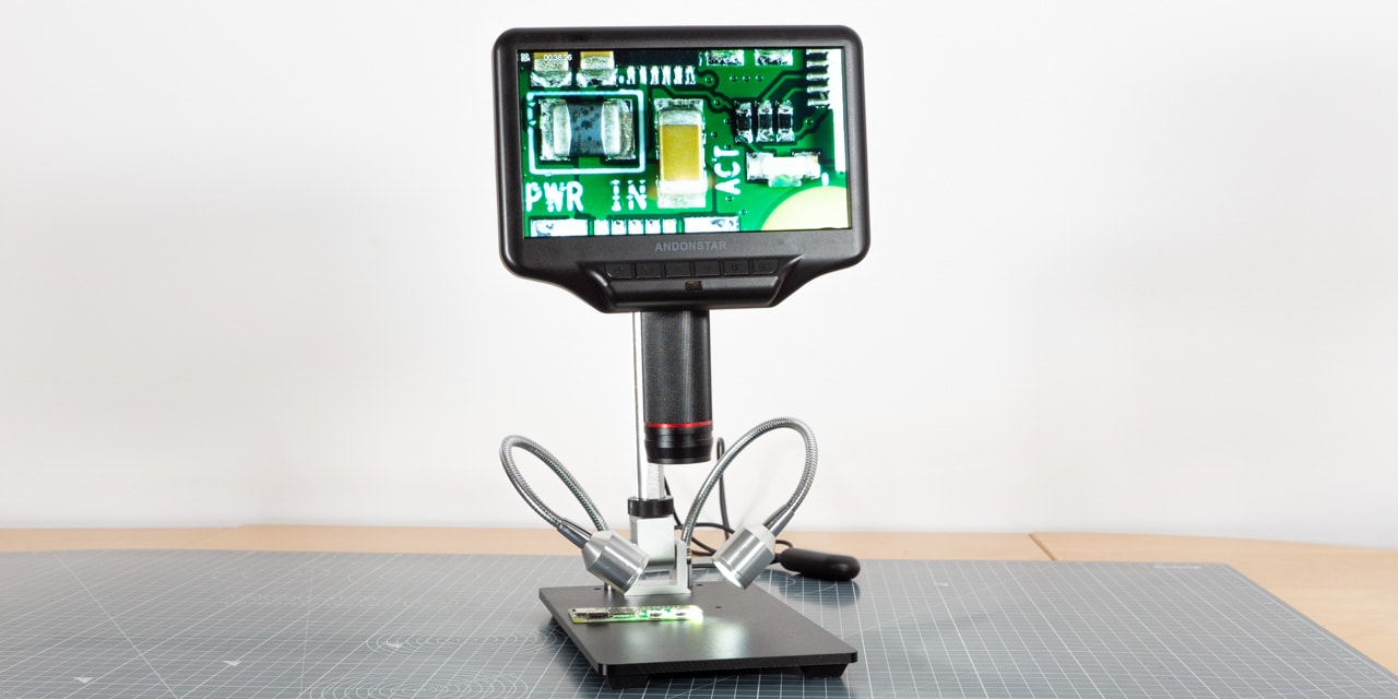
One example of such a device is the Andonstar AD407. It is a digital microscope that is often used for SMD work. It is the successor of the popular Andonstar ADSM302. It comes with a variety of features that make soldering SMD components a lot easier.
Let’s see if it is worth your money and how it compares to the ADSM302!
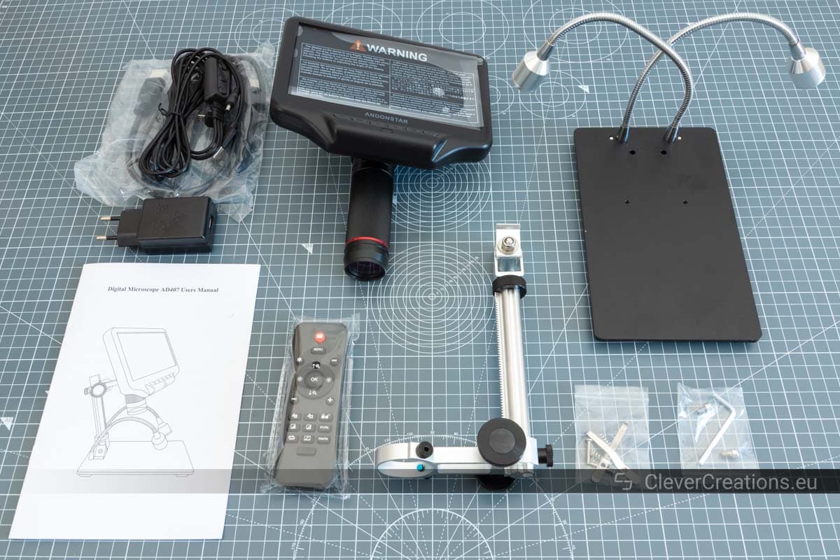
Unboxing
The box of the Andonstar AD407 contains the following:
- Base stand
- Adjustable arm
- Optical stack (consisting of the screen and the lens)
- UV filter (preinstalled on the lens)
- Small PCB clamps
- IR Remote (2*AAA batteries NOT included)
- Mini HDMI -> HDMI cable
- Switch cable
- Power adapter
- Manual
| Andonstar AD407 Specs | |
|---|---|
| Microscope type | Video |
| Magnification | Up to 270x (measured on a 27″ screen) |
| Minimum focus distance | 5 cm |
| HDMI Video output | UHD 2880 x 2160 (24 fps) FHD 1920 x 1080 (60 fps/30 fps) HD 1280 x 720 (120 fps) |
| Video format | MP4 |
| Photo resolution | Max. 4032*3024 |
| Photo format | JPG |
| Storage | Micro-SD card, max 32GB (NOT included) |
| Built-in display size | 7″ |
| Light source | 2 LED spots |
| Power source | 5V DC |
| Stand dimensions | 200 x 120 x 190 mm |
| Weight | 1.6 kg |
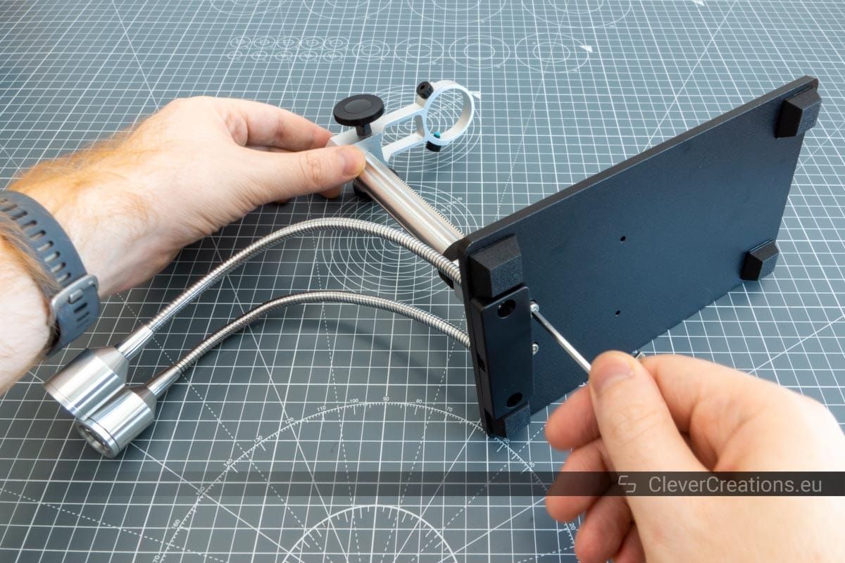
Assembly
Before you can use the AD407, you first need to assemble its parts. This may sound daunting, but it is relatively simple. It is a matter of screwing in a couple of bolts, clamping parts in place and plugging in cables. Here’s a quick how-to:

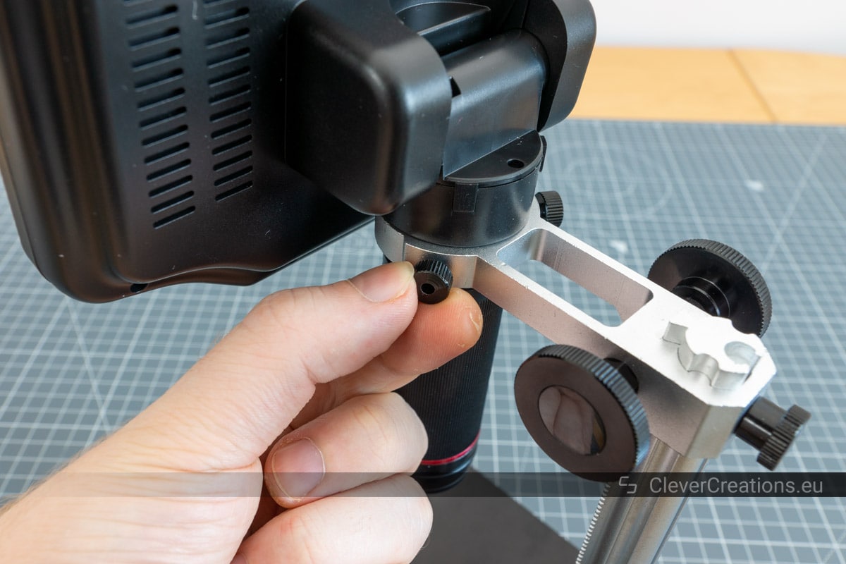
After this, you only have to plug in the cables, tear the protective film off of the LCD, and you are ready to go.
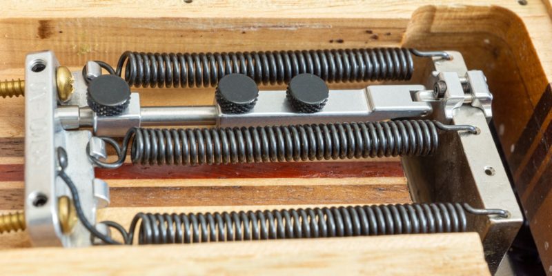
The box also contains a set of spring-loaded PCB clamps that you can attach to the base. These aren’t mentioned anywhere in the assembly instructions or manual. You can install them as follows:

Andonstar AD407 Features
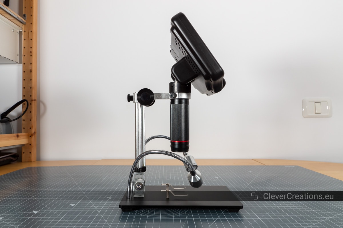
Adjustable Arm
The LCD screen and lens are mounted on an adjustable arm. This arm lets you not only move the lens up and down, but you also tilt it forwards and backwards. This gives you more vertical working area than with the lens right above your workpiece (more info on this later).
Andonstar markets the AD407 as a “3D” microscope, with the 3D effect coming from tilting the camera back and seeing more depth in the object. This stands in contrast with the “flat” image you see when you view an object straight from the top.
Now, I must admit that it is useful to view a workpiece from an angle sometimes. But you can also place the workpiece at an angle for that, under any digital microscope. For a true 3D microscope you need one with multiple lenses (binocular).
Vertical Working Space
With the lens raised to the top of the arm, there is about 80 mm of working space between the lens and the stand. From that, you will also have to subtract the height of the circuit board or whatever else you are working on.

This is not a whole lot of space, but there are ways to increase it. By tilting the arm back, for example, or by using the method in the next section.
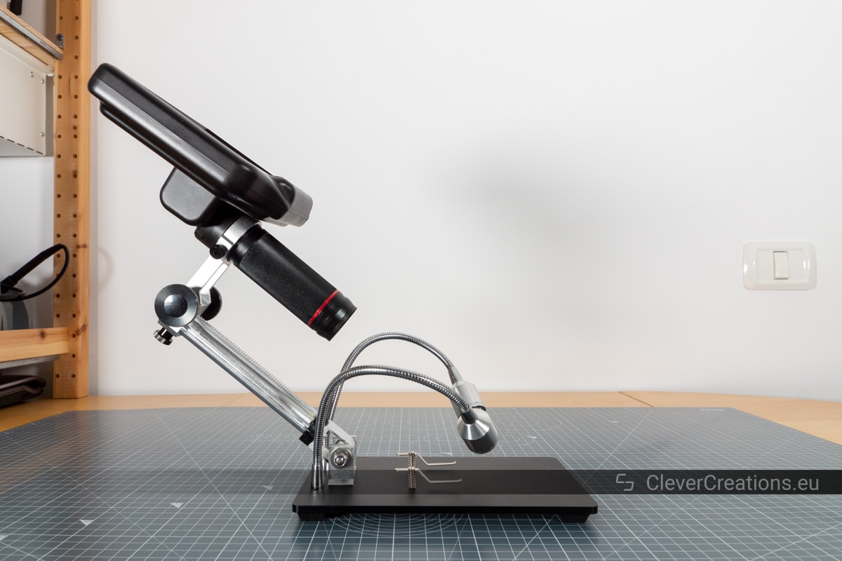
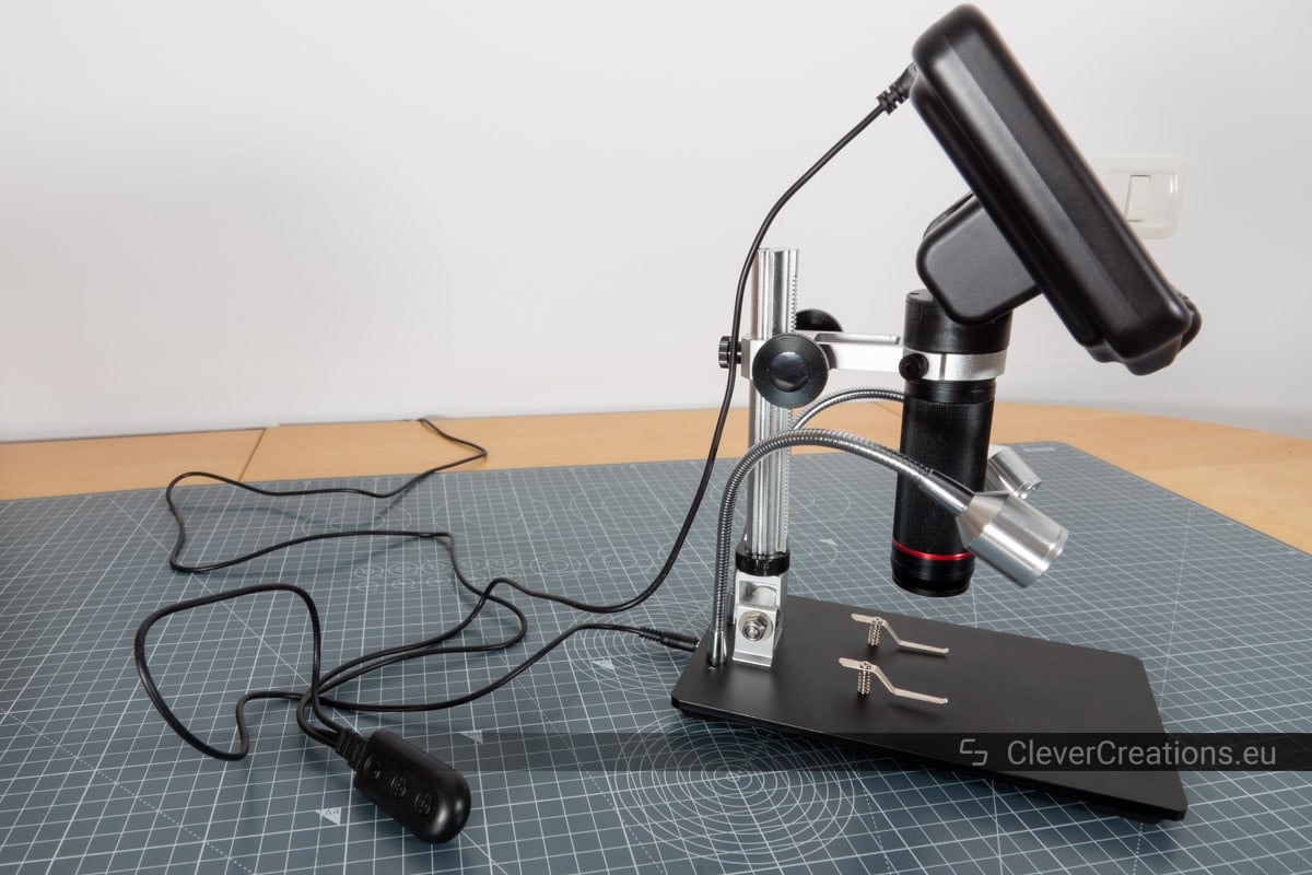
Alternative Mounting of the Lens
Another way to increase the working space is to install the lens by clamping it at the bottom, instead of at the top. The bottom of the lens has a fixed area that the thumbscrews can grab on to.
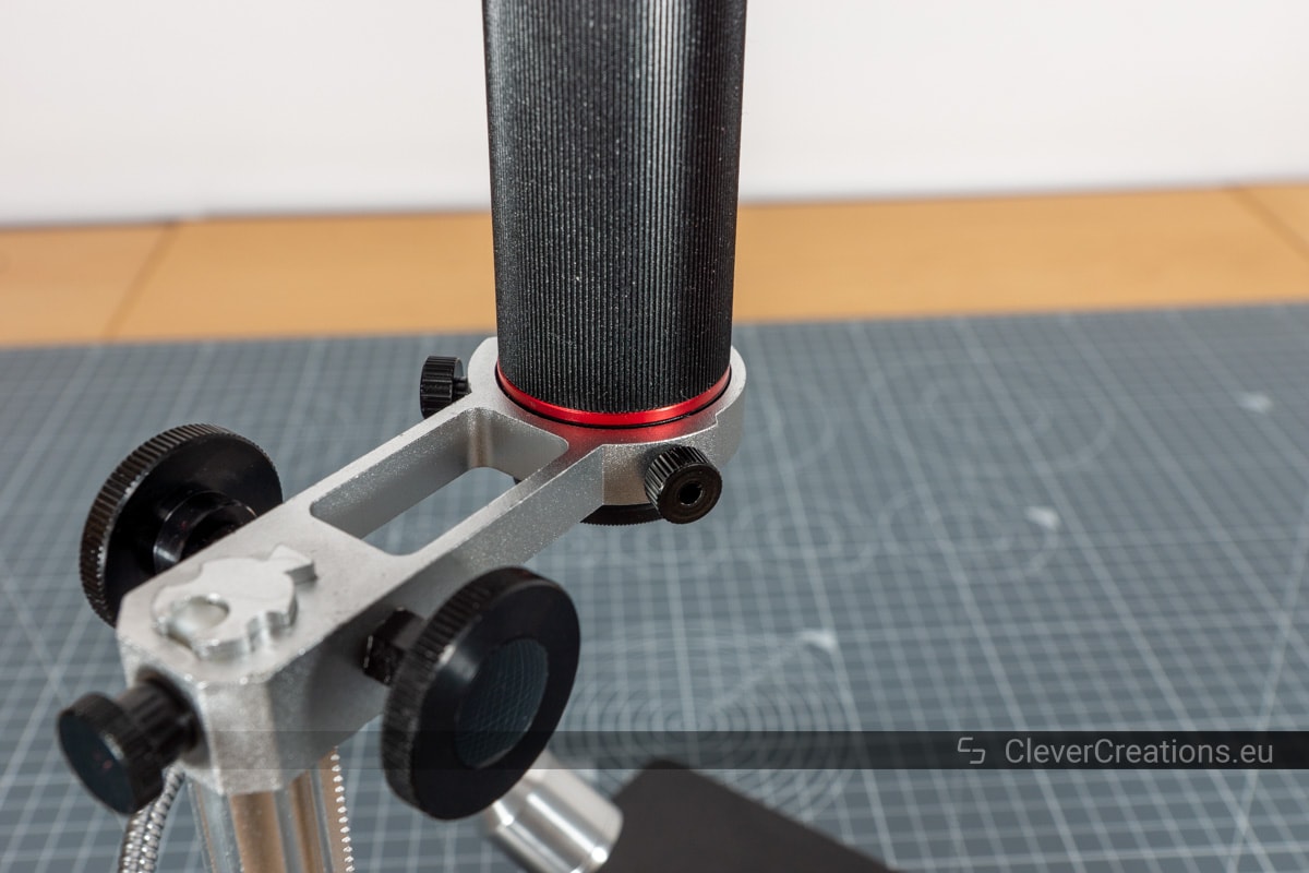
This more than doubles the working distance to 166 mm.
I am not sure if this is officially recommended, as the manual doesn’t mention anything about it, but I have found it to work just fine.
The only downside I experienced with this is that the microscope falls over backwards more easily with the arm in this position. This is because the center of gravity is now shifted further back. The aluminium base by itself does not weigh enough to counteract this.
This is not a problem you will run into often. There is little need to tilt the arm far back when you have this much vertical working space in the first place.
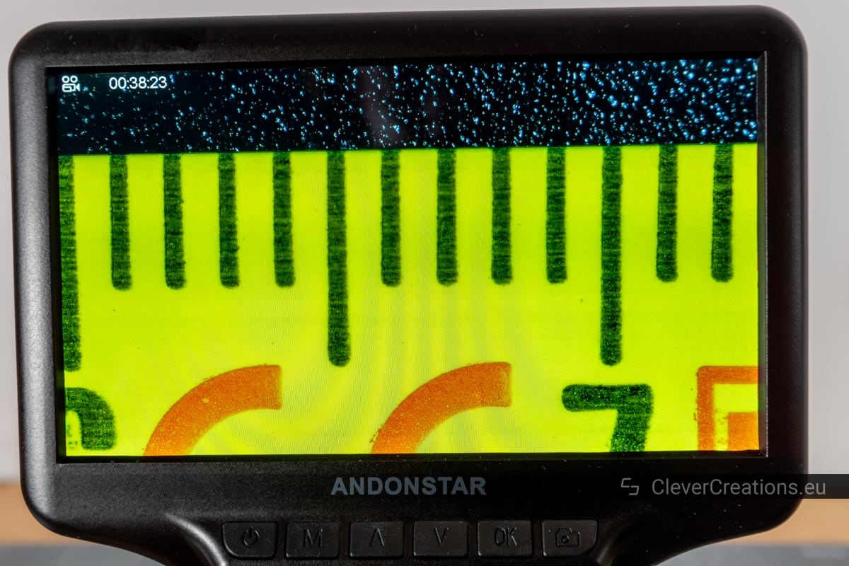
Focus Distance vs. Field of View
Adjusting the zoom and focus of the microscope is done by twisting the lens shaft and raising or lowering the lens on the arm. By doing this, you change the focus distance and field of view.
For each height you can set the lens to (focus distance), there is a specific size area (field of view) visible on the microscope LCD screen. I have listed them below, so that you can get an idea of how big of an area you can view at once under the microscope.
| Height | Focus distance | Field of view |
|---|---|---|
| Min. height | 50 mm | ~4 * 2 mm |
| Max. height | 80 mm | ~ 12.5 * 7 mm |
| Max. height – alternate lens mounting | 166 mm | ~ 25.5 * 14 mm |
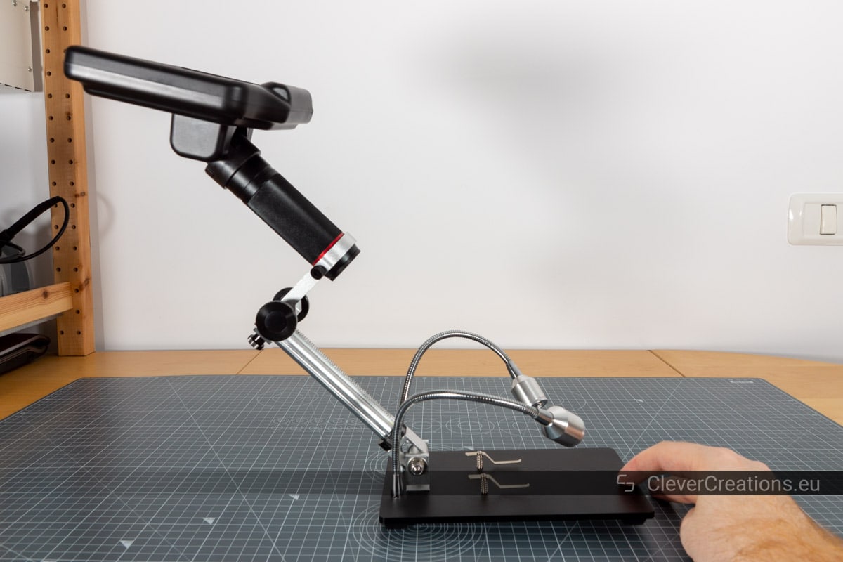
Base
The base stand of the AD407 is unfortunately a bit too lightweight. This results in the device tipping over backwards when you tilt the microscope arm back too far. Not ideal, and in that situation you will need to hold the base down by hand to keep it from tipping over.
With the base, you get two optional clamps that you can use to hold circuit boards in place. I do not find myself using them much, because they restrict the size of the horizontal work area.
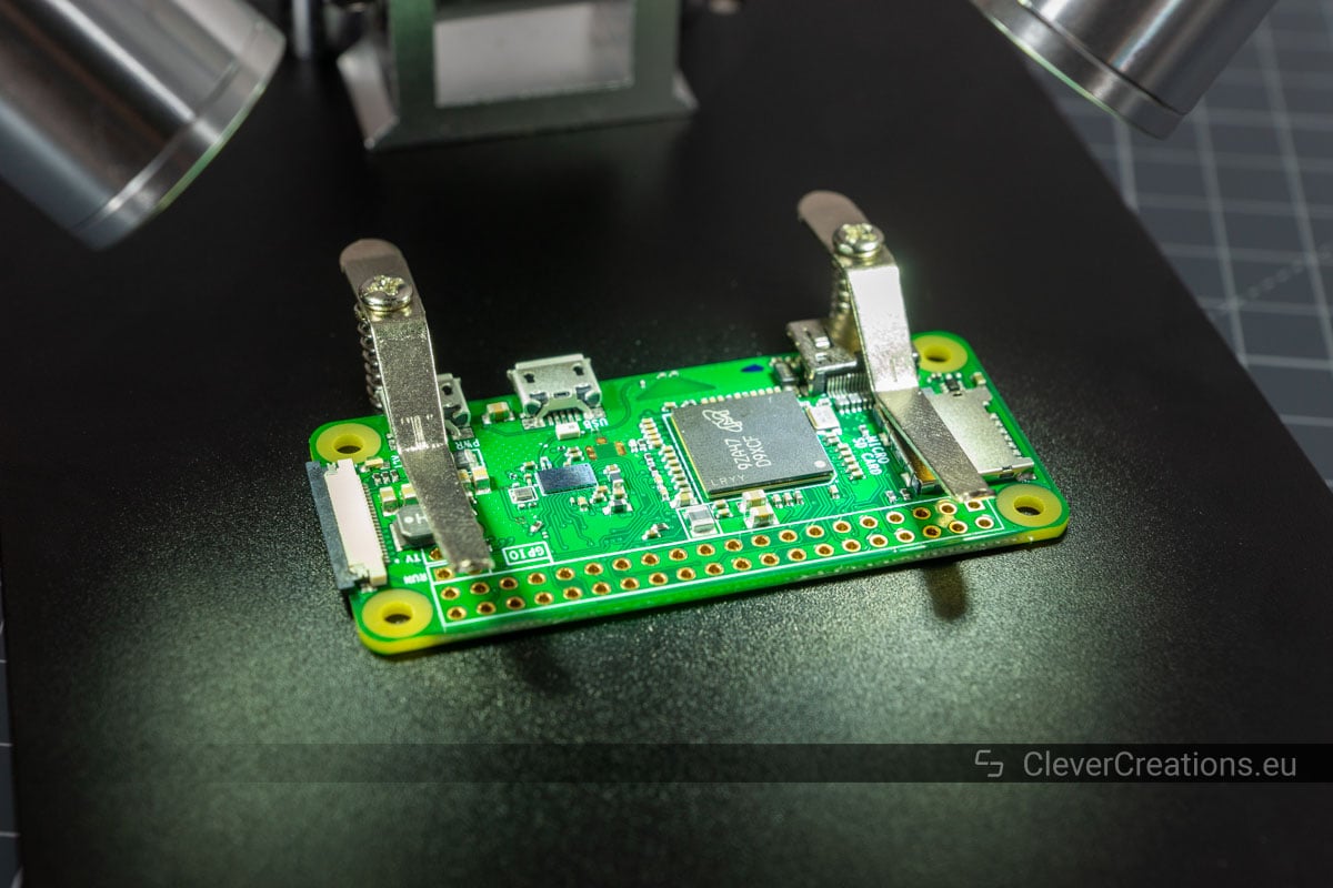
As for the adjustable LED lights on the stand, they are quite useful. You will need a good bit of light on your workpiece for it to be visible under the microscope. These lights give you exactly that.
The flexible arms of the lights are easy to adjust, yet stay in place well when not touched.
The brightness of the LEDs is adjustable in 8 steps through the wired switch on the power cable.
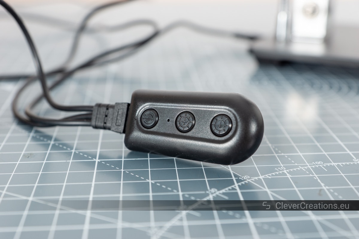
Image Quality
The Andonstar AD407 has three different methods you can use to work with the output image.
- The built-in 7″ LCD screen.
- On an external screen, through the HDMI output port.
- Save images or videos on a SD card (not included).
They do not all have the same quality, so I will go over them separately.
Built-in 7″ LCD Screen
The screen is probably the most valuable asset of this digital microscope. With its 7″ diagonal it is larger than the screen of the ADSM302 , which has a 5″ screen. The 7″ screen makes it easy to see small details.
I mainly tested the microscope with SMD soldering. For that, this screen works great. It is big enough not to need a larger, external monitor. This is often necessary when working with microscopes with smaller built-in monitors.
The LCD screen is quite responsive, so it responds fast to what is happening under the lens. This is especially important when soldering. You don’t want a delay between what you are doing under the lens and what you see on the screen.
The viewing angle of the screen is excellent as well. You don’t have to sit exactly in front of it to see what is going on. When looking from the sides or the top/bottom, the screen is still clear.

In terms of brightness, there is nothing to complain about either. With the default settings, objects under the lens are clearly visible on the screen.
If something does happen to be too dark or too light, you can adjust the exposure settings in the software. Or you can change the brightness of the LEDs that light up the workpiece.
HDMI Output
If you do want to see your work on a larger screen and in a higher resolution, you can use the HDMI output port. There is no setup involved. Plug the included HDMI cable into the microscope and the other end in your monitor, and you are good to go.
The HDMI output is clear and provides you with more detail than the built-in screen, which has a 1024×600 resolution. Usually the built-in screen is more than sufficient just by itself, however.
When using the HDMI output, the screen on the microscope itself still works. So you can use two screens at the same time. This feature was not supported on the ADSM302. On that microscope you could use either the built-in screen, or an external one.
Exporting Photos & Videos to the SD Card
If you want to take images or videos for later use, you can store them on a (non-included) SD card. This is done automatically when you press any of the record buttons on the remote or microscope.
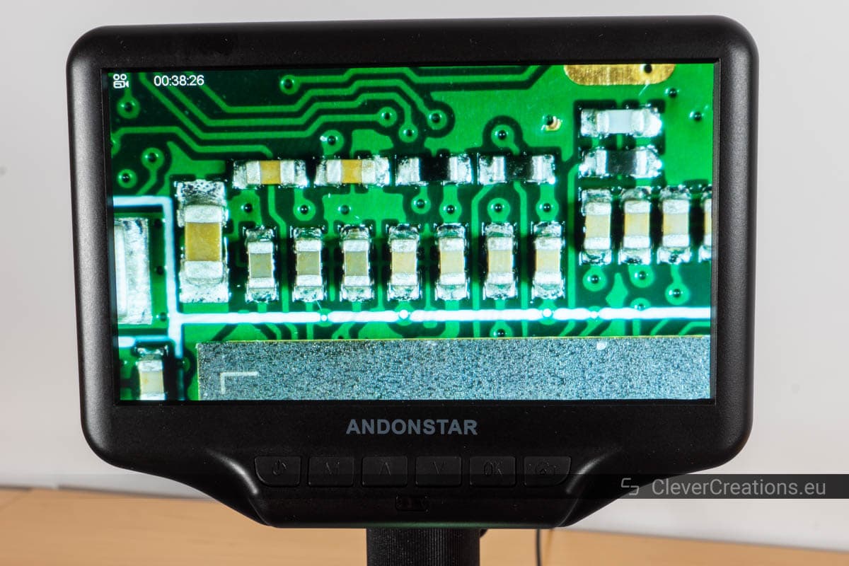
Photos
The quality of the photos is okay. They tend to be less sharp and more noisy than what you actually see on the built-in screen.
Stored images have a 4032*3024 (12 megapixel) resolution, despite the microscope only using a 4MP sensor. The images get upscaled to a higher resolution and do not have the same detail as a true 12MP image.
Photo Examples
You can click these to see the full resolution file.
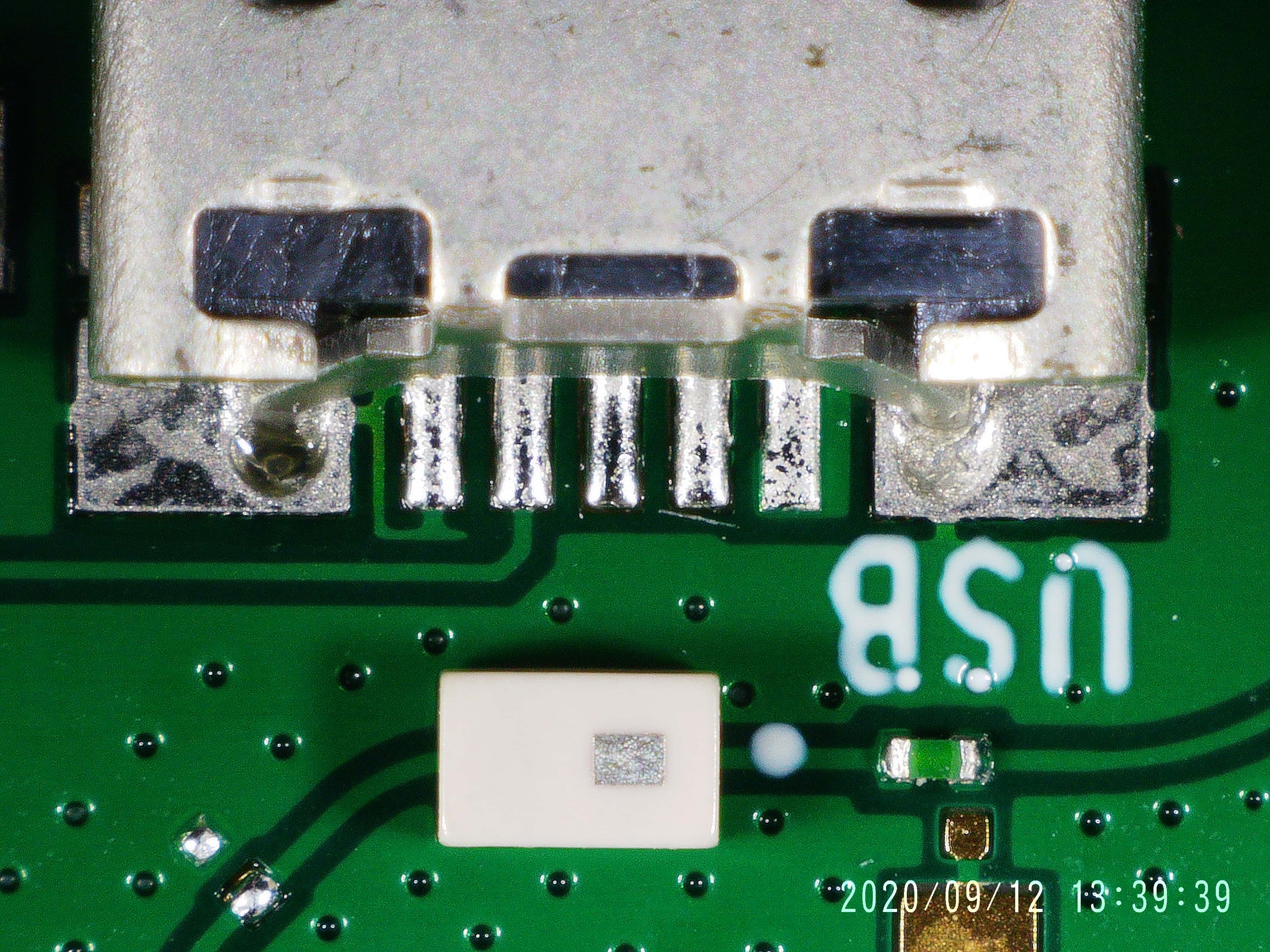
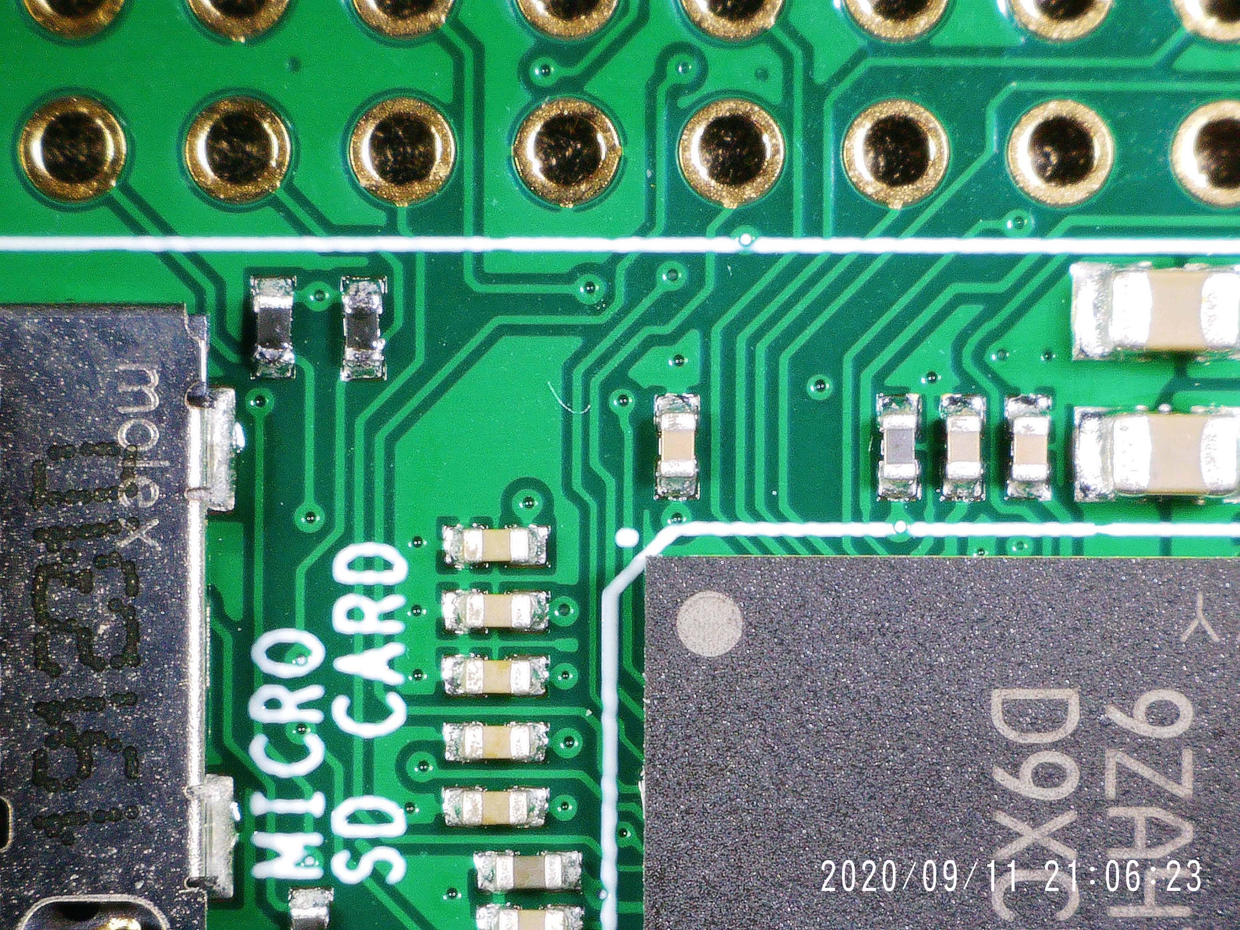
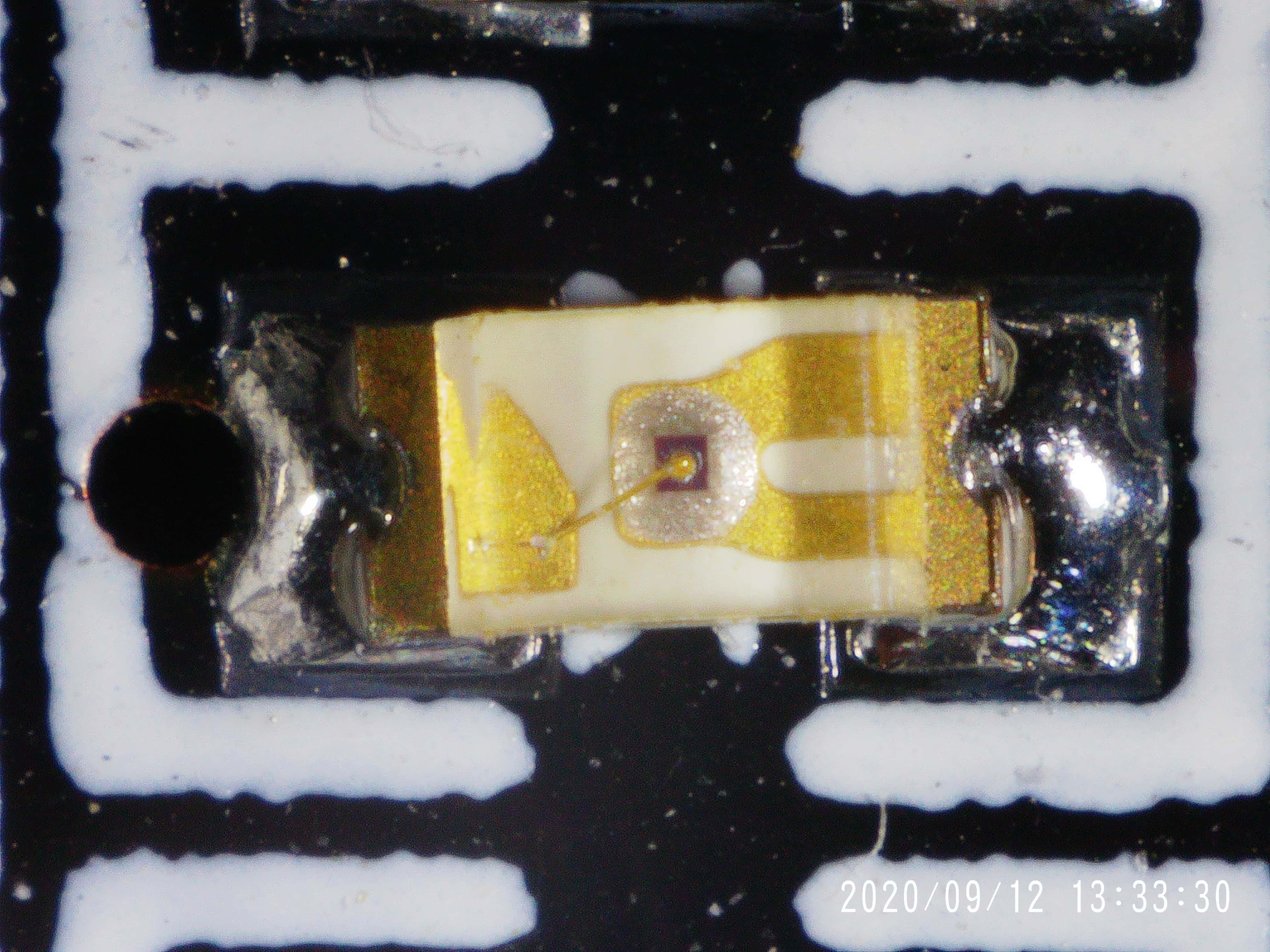
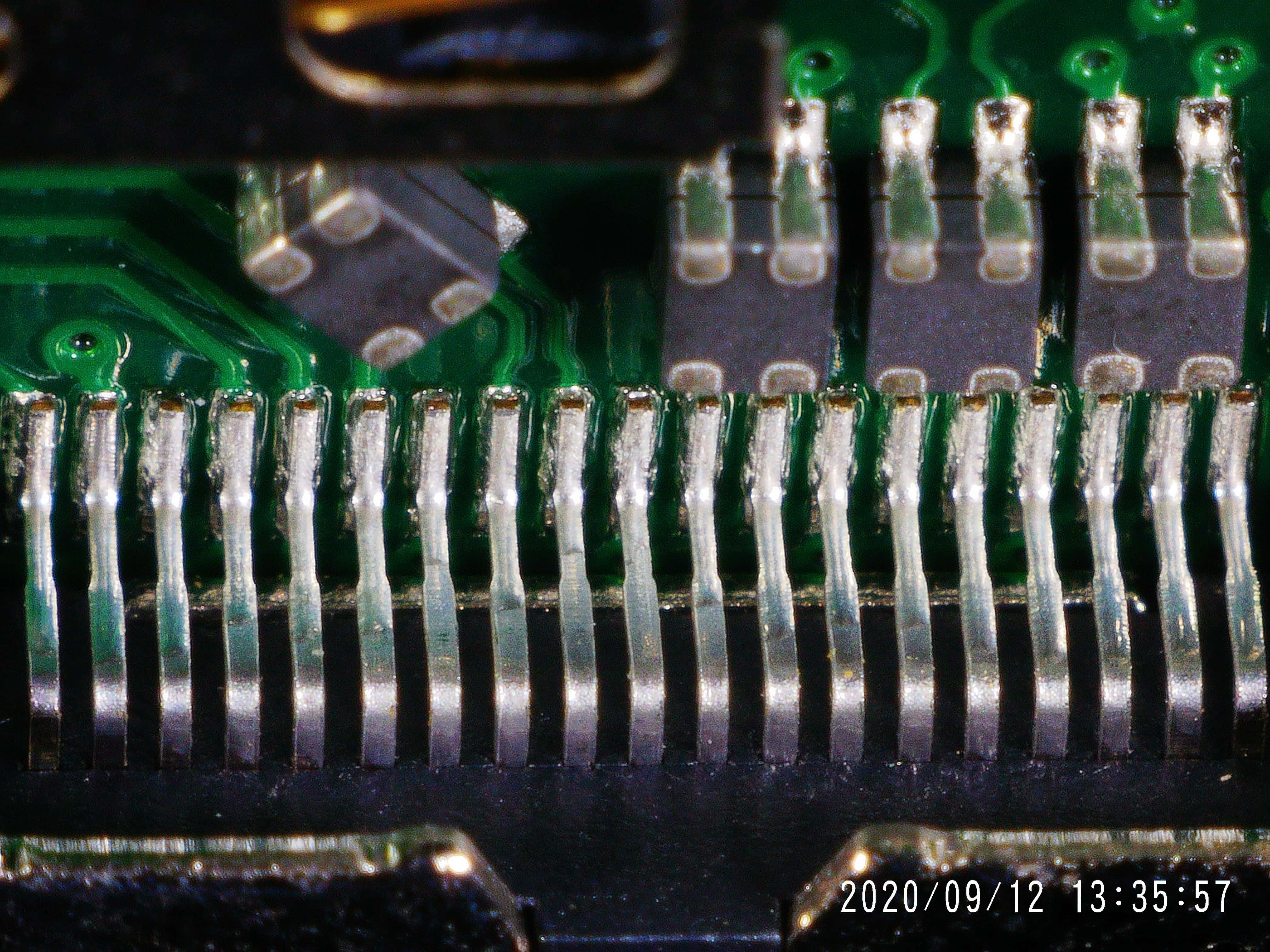
Another limitation of the images is that they are not taken from the ‘full’ screen. Instead, the frame is cut off at the sides and reduced to an image with a 4:3 aspect ratio (as opposed to the 16:9 ratio of the screen). Keep this in mind when framing your shots.
Videos
Aside from storing photos on the SD card, you can also make videos of what is visible under the microscope. They appear to be of better quality than the still images. With videos, you also have several resolutions and framerates to choose from.
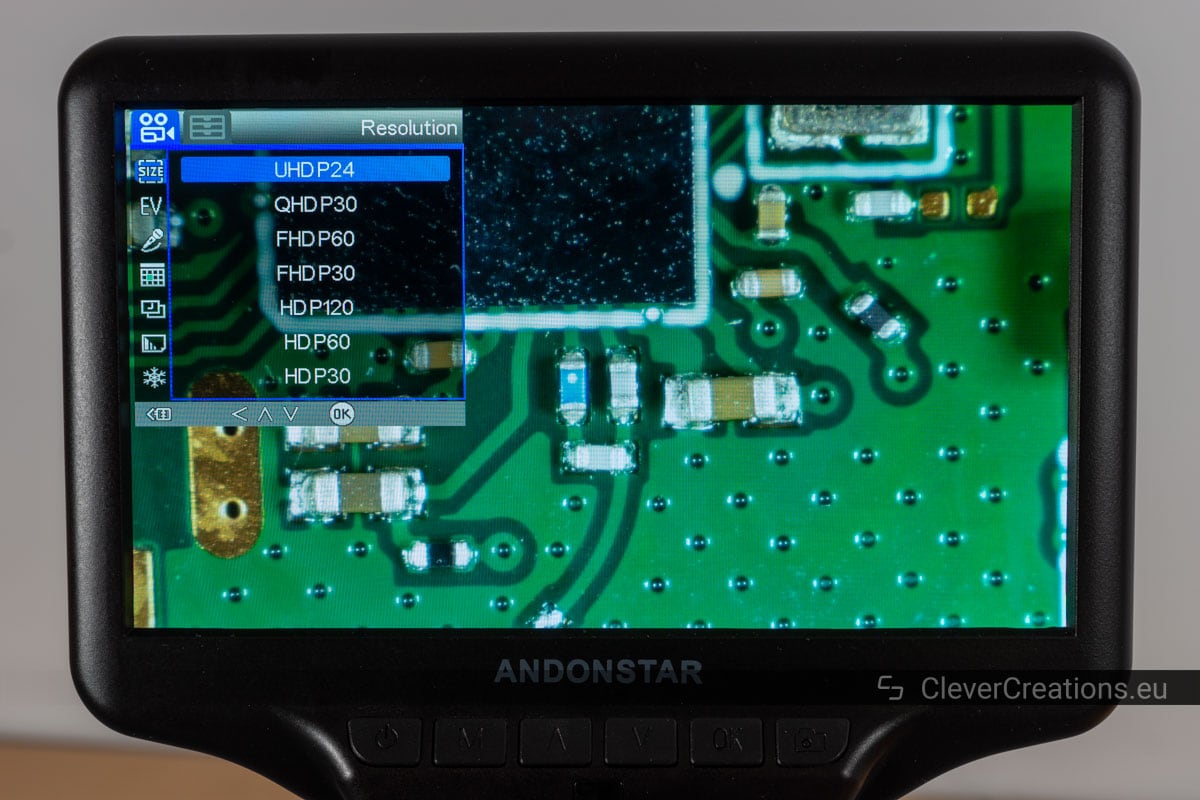
You can do this in the on-screen menu of the microscope. If you want the greatest resolution, you can pick the UHDP24 option (2880 x 2160 – 24 fps). If a high frame rate is more important to you, the best setting is HDP120 (1280 x 720 – 120 fps). As a solid middle ground, there is FHDP60 (1920 x 1080 – 60 fps).
As you can see, videos are saved in the full 16:9 aspect ratio, so no information gets cropped off like with images.
The video output format is limited to MP4 only. If you want to work with MPG, WEBM or a different format, you must first convert the video file in third party software.
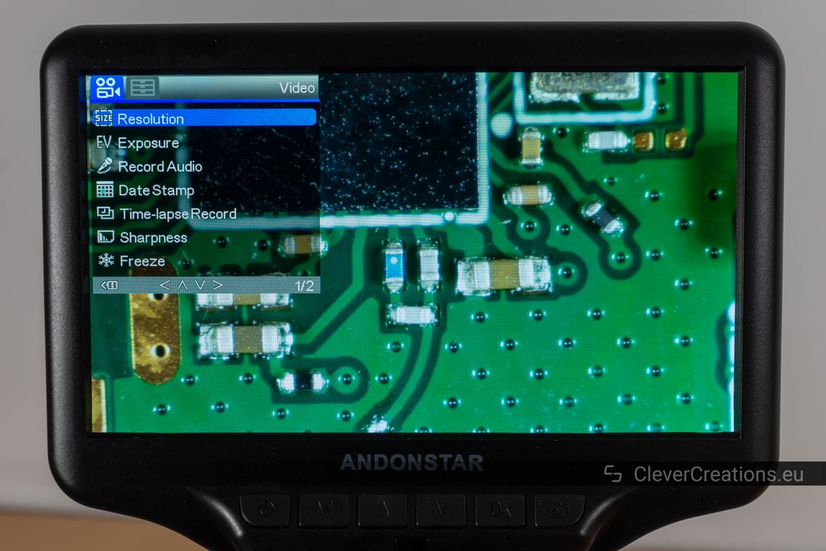
Software Options
The software of the microscope does what it is supposed to do. You can find several settings for controlling the video output (resolution/frame rate, output frequency, time stamp). There are additional settings that let you alter the image on the built-in screen (3x digital zoom and exposure control).
The 3x digital zoom is probably the most useful feature here. Because the 4 megapixel CMOS sensor resolution is higher than the 1024×600 resolution of the built-in LCD screen, you can zoom in without any loss in detail on the screen.
To properly store the settings, it is essential to ‘soft’ shutdown the microscope with the on/off button under the LCD screen. If you ‘hard’ shutdown by cutting the power using the cable switch, changed settings do not get stored.

Accessories
The Andonstar AD407 comes with several accessories that help improve your experience with the microscope.
Remote
The included remote is useful for making a photo (or video) without touching the buttons under the LCD screen. Using the buttons can cause movement, resulting in a blurry image. By using the remote you will not have this problem.
Similarly, you can use the remote to change the exposure settings without having to dive into the settings menu, and to adjust the digital zoom without using the hardware buttons. It is a useful addition to the microscope, but if you only use the microscope for SMD soldering you will likely not be using the remote much.

One downside of the remote is that (at least on my unit) I need to point the remote exactly at the IR receiver for it to work. So occasionally I need to re-aim and press the button again if nothing happens.
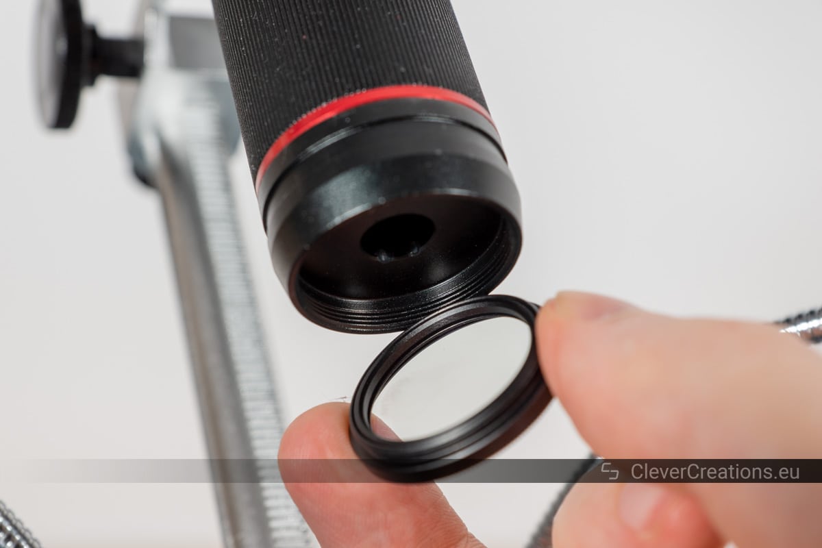
UV Filter
Also included is a UV filter. It is not used to filter out UV light however. Its main purpose is to protect the front lens element from soldering smoke and accidental damage. It makes for easier cleaning than if you would have to wipe down the tiny lens itself.
Drawbacks
I have saved most of the downsides of the AD407 for this section. There are quite a few, and they are mostly related to the build quality.
- Play in the height adjustment mechanism. The rack and pinion gear system that is used to raise and lower the microscope has wide tolerances and has some play to it. This doesn’t affect the actual use of the microscope, but it is an indicator of the overall construction quality of the device.
- Microscope tips over when tilting the arm too far back. The base of the microscope does not way enough. When the arm that holds the LCD screen and lens gets tilted back too far, it can cause the whole device to topple back.
- Adjustable arm is hard to adjust. A lot of force needs to be applied to the arm to move it backwards or forwards. On the plus side, this means that the arm won’t accidentally move when something bumps into the microscope.
- Messy wiring. The USB power input from the power adapter goes to the wired switch and from there it splits into two cables (one for the screen, one for the LED lights). This leads to a bit of a wire mess on your workbench.
A single-cable design from the adapter to the microscope would have been cleaner.
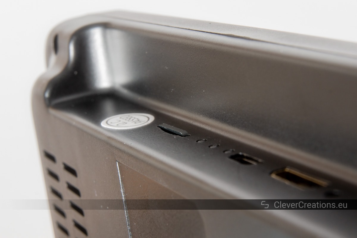
- SD card is hard to remove. If you insert a SD card in the SD card slot, it ends up almost flush with the surface of the device. To engage the spring mechanism to eject the card, the card needs to go down even futher. So to remove it, you need to put in a decent bit of effort to press exactly on the card with one of your nails.
In short, the build quality of this digital microscope could be improved in several ways. Despite that, the device is fully functional and does what it is supposed to do.
Andonstar AD407 vs ADSM302
If you are looking to buy a digital microscope with built-in screen, you might be wondering whether the Andonstar AD407 is a better option than the ADSM302. They are similar microscopes, but have a number of key differences.
Benefits of the AD407
The AD407, being the newer version, has better overall features. It comes with a bigger screen and is more responsive, making SMD soldering significantly easier. Its sensor also provides a higher resolution photos and videos than the one on the ADSM302.
Another benefit of the AD407 is the ability to use two screens (built-in and external) at the same time.
These features do come at a cost however, as the AD407 is about 20-25% more expensive than the ADSM302.
Benefits of the ADSM302
The ADSM302 on the other hand has a supposedly higher magnification. I say ‘supposedly’ because these claims should typically be taken with a grain of salt. The numbers are usually measured with digital magnification and on a large monitor. So it is more a case of blowing the image up to a large size than that the microscope actually resolves smaller details. An important difference.
A benefit that the ADSM302 does have is a higher maximum vertical working distance. About 120mm compared to the 80mm on the AD407. But with the AD407 you do have the possibility of tilting the lens backwards so that it does not get in the way. Plus you can increase the working distance by mounting the lens in a higher position on the arm, as described earlier in this review.
| Model | ADSM302 | AD407 |
|---|---|---|
| Max. video resolution | 1080P | 2160P |
| Max. frame rate | 30 fps | 120 fps |
| Display | 5″ | 7″ |
| Display resolution |
800×480 | 1024×600 |
| Max. magnification (claimed) | 560x | 270x |
| Sensor | 3MP | 4MP |
| Interfaces | USB, HDMI, AV | HDMI |
All in all, I would say that the improved features of the AD407 are worth the extra cost compared to the ADSM302.
Final Verdict: Should You Buy the Andonstar AD407?
Despite its flaws, the Andonstar AD407 is still one the best digital microscopes in its price range. Its build quality could be better, but in terms of features and optical qualities it provides good value. And as far as Chinese digital microscopes go, this is one the best options available right now.
Its compact size and ability to be used stand-alone without external monitor make it a practical microscope for a small electronics lab. If you are looking for a digital microscope for 0805, 0603 or even 0402 size SMD soldering, PCB inspection, general electronics work or gemstone setting, this is an excellent choice.
I want to try screwing on a 20x objective lens to the bottom to increase the magnification. The objective lens that I have is about 20mm thread size.
What is the thread diameter of the uv lens? Have you tried using an objective lens instead of the uv filter?
Hi Kenny,
I have measured the thread of the UV lens for you and it is 30 mm in diameter (29.77 mm to be exact). The bottom of the microscope has 2.5 mm of thread depth available.
I do not have any 30 mm objective lenses here, so I haven’t tried attaching one.
Tim
Hi Kenny,
were you able to try the additional lens? How did it work and which lens did you use?
Jan
Fantastic review. Well done. One question, is there available a longer horizontal arm? If not, can i buy the typical one as a spare part and then try to lengthen it using DIY metal strip or bar? All of my pcb are bigger than the available space. Thank you.
Thank you for your feedback!
There is no longer arm available, but what you can do is detach the arm from the heavy base and attach it onto something else using the included bolts. To a metal/wooden bar or anything else that is high enough. It shouldn’t be too difficult to DIY something for that.
I have the same need. 3/4″ baltic birch plywood is a snug fit in the yoke. I am going to cut the horizontal arm through yoke and make an extension of a few inches then drill 2 holes in each half to secure.
Maybe this works well!!
Excellent review. Can a Barlow lens be attached to the bottom (0.3 or 0.5) to increase field of view at a normal height above the work surface? What are the advantages of a stereo microscope over this (pro and con)?
Thanks, Larry. It should be possible to attach a Barlow lens, provided you can find one with the right thread size (30mm).
Compared to digital microscopes, stereo microscopes have increased image quality, let you see depth, and tend to be more durable. They are significantly larger and more expensive, however.
A digital microscope also allows you to work sitting straight, as opposed to hunched over the microscope like with an optical one.